
Cisco Gigabit Ethernet Switch Module for HP BladeSystem p-Class Hardware Installation Guide

Switch Installation
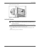
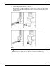
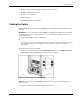
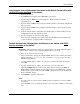
3. Insert the end of the cable-retaining bracket (provided with the bus bar and power bus
boxes) into the cable bracket (1).
4. Tighten the thumbscrew to secure the cable-retaining bracket over the cables (2).
Figure 2-5: Installing the Cable-retaining Bracket
5. Repeat steps 2 through 4 for the network cables on the left side of the rack.
Accessing the Switch for the First Time
For initial configuration, the switch can be accessed locally from a workstation connected to
its console port or remotely from a workstation on the network attached to any of its Ethernet
ports. Depending on whether or not the switch is connected to an Ethernet network with
DHCP service for IP configuration, there are multiple methods for configuring it. Depending
on your current setup, choose and execute the right method described below.
Local Access from a Workstation Connected to the Switch Console Port with
DHCP Service Available
to the Switch
IMPORTANT: Accessing the switch locally when there is a DHCP server requires that the switch
obtain its DHCP-supplied IP address before beginning the configuration procedure.
1. Power up the switch.
2. Do not press Enter when prompted to "Press RETURN to get started!”
As the switch boots, it brings up all the interfaces.
3. Press Enter when “AUTOINSTALL: VLAN1 is assigned xxx.xxx.xxx.xxx” is displayed
(where xxx.xxx.xxx.xxx represents a DHCP-assigned address).
4. Press Enter when prompted, “Would you like to terminate autoinstall? [yes]:”
After pressing Enter, the switch enters the User EXEC mode and displays the "Switch>"
prompt for further configuration.
2-10 Cisco Gigabit Ethernet Switch Module for HP BladeSystem p-Class Hardware Installation Guide