
Cisco Gigabit Ethernet Switch Module for HP BladeSystem p-Class Hardware Installation Guide

Troubleshooting
Replacing an Existing Cisco Gigabit Ethernet Switch Module
CAUTION: Removing a switch from a powered enclosure will result in the loss of network
communications between the server blade network ports that are connected through this
switch and the segment of network infrastructure those ports need to communicate.
For continued blade server network communication and services availability, do the following
before you remove the switch. Redirect critical high-availability services or applications to use
the redundant network ports available on those blade servers that are connected through the
redundant switch in the enclosure.
CAUTION: To prevent damage to the cable connectors and SFP modules, be sure to take
the following steps before removing or installing the blade switch:
1. Disconnect the cables from the SFP modules.
2. Remove the SFP modules from the blade switch.
IMPORTANT: If you are replacing an existing CGESM, or upgrading from a GbE2 Interconnect Switch,
a GbE Interconnect Switch, an RJ-45 Patch Panel 2, or an RJ-45 Patch Panel, and you have strict
security requirements:
• Do not cable the switch until after configuration.
Or
• Connect the switch to the optional Diagnostic Station. The Diagnostic Station enables you to power
up, configure, and diagnose a ProLiant p-Class server blade or a switch outside of the rack
environment.
To replace an existing CGESM:
1. If possible, save the configuration file to a TFTP server for later retrieval. For more
information on saving a configuration file to a TFTP server, refer to the Cisco Gigabit
Ethernet Switch Module for HP BladeSystem p-Class Software Configuration Guide
located on the HP website at
http://www.hp.com/support.
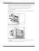
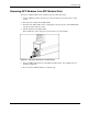
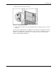
2. Disconnect any cables from the SFP modules on the rear side of the switch.
3. Remove the SFP modules.
4-4 Cisco Gigabit Ethernet Switch Module for HP BladeSystem p-Class Hardware Installation Guide