
Cisco Gigabit Ethernet Switch Module for HP p-Class BladeSystem Software Configuration Guide


7-4
Cisco Gigabit Ethernet Switch Module for HP p-Class BladeSystem Software Configuration Guide
380261-003
Chapter 7 Configuring Interface Characteristics
Using Interface Configuration Mode
Connecting Interfaces
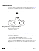
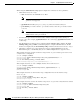
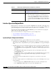
Devices within a single VLAN can communicate directly through any switch. Ports in different VLANs
cannot exchange data without going through a routing device. In the configuration shown in Figure 7-1,
when Blade Server A in VLAN 20 sends data to Blade Server B in VLAN 30, the data must go from
Blade Server A to the switch, to the router, back to the switch, and then to Blade Server B.
Figure 7-1 Connecting VLANs with Layer 2 Switches
Using Interface Configuration Mode
The switch supports these interface types:
• Physical ports—switch ports
• VLANs—switch virtual interfaces
• Port channels—EtherChannel interfaces
You can also configure a range of interfaces (see the “Configuring a Range of Interfaces” section on
page 7-6).
To configure a physical interface (port), specify the interface type, module number, and switch port number,
and enter interface configuration mode.
• Type—Gigabit Ethernet (gigabitethernet or gi) for 10/100/1000 Mb/s Ethernet port or small
form-factor pluggable (SFP) module Gigabit Ethernet interfaces.
• Module number—The module or slot number on the switch (always 0 on theswitch).
You can identify physical interfaces by physically checking the interface location on the switch. You
can also use the show privileged EXEC commands to display information about a specific interface or
all the interfaces on the switch. The remainder of this chapter primarily provides physical interface
configuration procedures.
Blade
Server A
Blade Switch
Cisco router
VLAN 20 VLAN 30
119645
Blade
Server B