
Cisco Gigabit Ethernet Switch Module for HP p-Class BladeSystem Software Configuration Guide

13-12
Cisco Gigabit Ethernet Switch Module for HP p-Class BladeSystem Software Configuration Guide
380261-003
Chapter 13 Configuring MSTP
Understanding RSTP
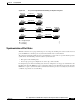
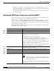
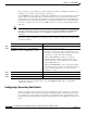
After ensuring that all of the ports are synchronized, the switch sends an agreement message to the
designated switch corresponding to its root port. When the switches connected by a point-to-point link
are in agreement about their port roles, the RSTP immediately transitions the port states to forwarding.
The sequence of events is shown in Figure 13-5.
Figure 13-5 Sequence of Events During Rapid Convergence
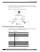
Bridge Protocol Data Unit Format and Processing
The RSTP BPDU format is the same as the IEEE 802.1D BPDU format except that the protocol version
is set to 2. A new 1-byte Version 1 Length field is set to zero, which means that no version 1 protocol
information is present. Table 13-3 shows the RSTP flag fields.
2. Block
9. Forward
1. Proposal4. Agreement
6. Proposal
Root port
Designated port
8. Agreement 10. Agreement
Edge port
7. Proposal
5. Forward
3. Block
11. Forward
88761
Table 13-3 RSTP BPDU Flags
Bit Function
0 Topology change (TC)
1 Proposal
2–3:
00
01
10
11
Port role:
Unknown
Alternate port
Root port
Designated port
4Learning
5Forwarding
6 Agreement
7 Topology change acknowledgement (TCA)