
Cisco Gigabit Ethernet Switch Module for HP p-Class BladeSystem Software Configuration Guide


17-4
Cisco Gigabit Ethernet Switch Module for HP p-Class BladeSystem Software Configuration Guide
380261-003
Chapter 17 Configuring IGMP Snooping and MVR
Understanding IGMP Snooping
Router A sends a general query to the switch, which forwards the query to ports 2 through 5, which are
all members of the same VLAN. Blade Server 1 wants to join multicast group 224.1.2.3 and multicasts
an IGMP membership report (IGMP join message) to the group. The switch CPU uses the information
in the IGMP report to set up a forwarding-table entry, as shown in Table 17-1, that includes the port
numbers of Blade Server 1 and the router.
The switch hardware can distinguish IGMP information packets from other packets for the multicast
group. The information in the table tells the switching engine to send frames addressed to the 224.1.2.3
multicast IP address that are not IGMP packets to the router and to the host that has joined the group.
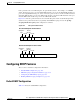
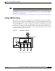
If another blade server (for example, Blade Server 4) sends an unsolicited IGMP join message for the
same group (Figure 17-2), the CPU receives that message and adds the port number of Blade Server 4 to
the forwarding table as shown in Table 17-2. Note that because the forwarding table directs IGMP
messages only to the CPU, the message is not flooded to other ports on the switch. Any known multicast
traffic is forwarded to the group and not to the CPU.
Figure 17-2 Second Host Joining a Multicast Group
Table 17-1 IGMP Snooping Forwarding Table
Destination Address Type of Packet Ports
224.1.2.3 IGMP 1, 2
Table 17-2 Updated IGMP Snooping Forwarding Table
Destination Address Type of Packet Ports
224.1.2.3 IGMP 1, 2, 5
Forwarding
table
CPU
Router A
Switching engine
VLAN
19
0
135 7
119648
Blade
Server 1
Blade
Server 2
Blade
Server 3
Blade
Server 4