
Cisco Gigabit Ethernet Switch Module for HP p-Class BladeSystem Software Configuration Guide

27-31
Cisco Gigabit Ethernet Switch Module for HP p-Class BladeSystem Software Configuration Guide
380261-003
Chapter 27 Configuring QoS
Configuring Standard QoS
Default Egress Queue Configuration
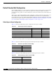
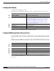
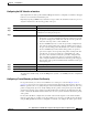
Table 27-9 shows the default egress queue configuration for each queue-set when QoS is enabled. All
ports are mapped to queue-set 1. The port bandwidth limit is set to 100 percent and rate unlimited.
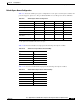
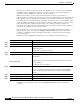
Table 27-10 shows the default CoS output queue threshold map when QoS is enabled.
Table 27-11 shows the default DSCP output queue threshold map when QoS is enabled.
Table 27-9 Default Egress Queue Configuration
Feature Queue 1 Queue 2 Queue 3 Queue 4
Buffer allocation 25 percent 25 percent 25 percent 25 percent
WTD drop threshold 1 100 percent 200 percent 100 percent 100 percent
WTD drop threshold 2 100 percent 200 percent 100 percent 100 percent
Reserved threshold 50 percent 50 percent 50 percent 50 percent
Maximum threshold 400 percent 400 percent 400 percent 400 percent
SRR shaped weights
(absolute)
1
1. A shaped weight of zero means that this queue is operating in shared mode.
25 0 0 0
SRR shared weights
2
2. One quarter of the bandwidth is allocated to each queue.
25 25 25 25
Table 27-10 Default CoS Output Queue Threshold Map
CoS Value Queue ID–Threshold ID
0, 1 2–1
2, 3 3–1
4 4–1
5 1–1
6, 7 4–1
Table 27-11 Default DSCP Output Queue Threshold Map
DSCP Value Queue ID–Threshold ID
0–15 2–1
16–31 3–1
32–39 4–1
40–47 1–1
48–63 4–1