
Cisco Gigabit Ethernet Switch Module for HP p-Class BladeSystem Software Configuration Guide

28-18
Cisco Gigabit Ethernet Switch Module for HP p-Class BladeSystem Software Configuration Guide
380261-003
Chapter 28 Configuring EtherChannels and Layer 2 Trunk Failover
Understanding Layer 2 Trunk Failover
In a link-state group, the link states of the downstream interfaces are dependent on the link states of the
upstream interfaces. If all of the upstream interfaces in a link-state group are in the link-down state, the
associated downstream interfaces are forced into the link-down state. If any one of the upstream
interfaces in the link-state group is in a link-up state, the associated downstream interfaces can change
to or remain in the link-up state.
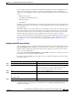
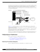
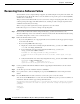
Figure 28-4 Typical Layer 2 Trunk Failover Configuration
In Figure 28-4, downstream interfaces 1, 3, and 5 are defined in link-state group 1 with upstream
interfaces 19 and 20. Similarly, downstream interfaces 2, 4, and 6 are defined in link-state group 2 with
upstream interfaces 21 and 22.
If link is lost on upstream interface 19, the link states of downstream interfaces 1, 3, and 5 do not change.
If upstream interface 20 also loses link, downstream interfaces 1, 3 and 5 go into a link-down state.
Downstream interfaces 2, 4, and 6 do not change states.
You can recover a downstream interface link-down condition by removing the failed downstream port
from the link-state group. To recover multiple downstream interfaces, disable the link-state group.
Configuring Layer 2 Trunk Failover
These sections describe how to configure trunk failover ports:
• Default Layer 2 Trunk Failover Configuration, page 28-18
• Layer 2 Trunk Failover Configuration Guidelines, page 28-19
• Configuring Layer 2 Trunk Failover, page 28-19
Default Layer 2 Trunk Failover Configuration
There are no link-state groups defined, and trunk failover is not enabled for any group.
BladeCenter
For example
Catalyst 3550 Switch
92356
Do
w
nstream
interface
1
Li
n
k
-s
t
a
t
e group
1
Upstream interface 17
Upstream interface 18
Link-state group 2
Upstream interface 19
Upstream interface 20
Cisco
ESM
Downstream interface 2
Downstream interface 3
Downstream interface 4
Downstream interface 5
Downstream interface 6
Network