Cisco Gigabit Ethernet Switch Module for HP p-Class BladeSystem System Message Guide Cisco IOS Release 12.
© 2005–2009 Hewlett-Packard Development Company, L.P. Microsoft®, Windows®, and Windows NT® are trademarks of Microsoft Corporation in the U.S. and other countries. Cisco® is a registered trademark of Cisco Systems, Inc. and/or its affiliates in the U.S. and certain other countries. SunOS™, Solaris™, and Java™ are trademarks of Sun Microsystems, Inc. in the U.S. and other countries. SecureCRT® is a registered trademark of VanDyke Software, Inc. in the U.S. and/or other countries.
CONTENTS Preface v Audience Purpose v v Conventions v Related Publications vi Obtaining Documentation and Submitting a Service Request CHAPTER 1 System Message Overview 1-1 How to Read System Messages 1-1 Error Message Traceback Reports Output Interpreter 1-5 Bug Toolkit 1-5 Contacting TAC 1-5 CHAPTER 2 1-5 Message and Recovery Procedures ACLMGR Messages 2-2 BSPATCH Messages 2-6 CGESM Messages CMP Messages 2-1 2-7 2-8 DHCP_SNOOPING Messages DOT1X Messages DTP Messages 2-9 2-12 D
Contents IGMP_QUERIER Messages 2-28 MAC_LIMIT Messages 2-29 MAC_MOVE Messages 2-30 PAGP_DUAL_ACTIVE Messages PHY Messages 2-31 PLATFORM Messages 2-32 PLATFORM_PM Messages 2-33 PLATFORM_VLAN Messages PM Messages 2-34 2-35 PORT_SECURITY Messages QOSMGR Messages RMON Messages SPAN Messages 2-30 2-43 2-44 2-49 2-49 SPANTREE Messages 2-50 SPANTREE_FAST Messages 2-58 SPANTREE_VLAN_SW Messages STORM_CONTROL Messages SUPERVISOR Messages SUPQ Messages 2-58 2-59 2-59 SW_MACAUTH Messages S
Preface Audience This guide is for the networking professional managing the Cisco Gigabit Ethernet Switch Module (CGESM) for FSC, hereafter referred to as the switch. Before using this guide, you should have experience working with the Cisco IOS software and the switch software features. Purpose This guide describes the Cisco Gigabit Ethernet Switch Module (CGESM)-specific system messages that you might encounter.
Preface Interactive examples use these conventions: • Terminal sessions and system displays are in screen font. • Information you enter is in boldface screen font. • Nonprinting characters, such as passwords or tabs, are in angle brackets (< >). Notes use this convention and symbol: Note Means reader take note. Notes contain helpful suggestions or references to materials not in this manual.
CH A P T E R 1 System Message Overview This guide describes the switch system messages. During operation, the system software sends these messages to the console (and, optionally, to a logging server on another system). Not all system messages mean problems with your system. Some messages are informational, and others can help diagnose problems with communications lines, internal hardware, or the system software.
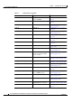
Chapter 1 System Message Overview How to Read System Messages Table 1-1 Facility Codes (continued) Facility Code Description Location CGESM Cisco Gigabit Ethernet Switch Module (CGESM) “CGESM Messages” section on page 2-7 CMP Cluster Membership Protocol “CMP Messages” section on page 2-8 DHCP_SNOOPING DHCP snooping “DHCP_SNOOPING Messages” section on page 2-9 DOT1X IEEE 802.1x “DOT1X Messages” section on page 2-12 DOT1X_SWITCH IEEE 802.
Chapter 1 System Message Overview How to Read System Messages Table 1-1 Facility Codes (continued) Facility Code Description Location PLATFORM Low-level platform-specific “PLATFORM Messages” section on page 2-32 PLATFORM_PM Platform port manager “PLATFORM_PM Messages” section on page 2-33 PLATFORM_VLAN Platform VLAN “PLATFORM_VLAN Messages” section on page 2-34 PM Port manager “PM Messages” section on page 2-35 PORT_SECURITY Port security “PORT_SECURITY Messages” section on page 2-43 Q
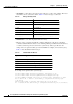
Chapter 1 System Message Overview How to Read System Messages • SEVERITY is a single-digit code from 0 to 7 that reflects the severity of the condition. The lower the number, the more serious the situation. Table 1-2 lists the message severity levels. Table 1-2 Message Severity Levels Severity Level Description 0 – emergency System is unusable. 1 – alert Immediate action required. 2 – critical Critical condition. 3 – error Error condition. 4 – warning Warning condition.
Chapter 1 System Message Overview Error Message Traceback Reports Error Message Traceback Reports Some messages describe internal errors and contain traceback information. Include this information when you report a problem to your technical support representative. This message example includes traceback information: -Process= "Exec", level= 0, pid= 17 -Traceback= 1A82 1AB4 6378 A072 1054 1860 Some system messages ask you to copy the error messages and take further action.
Chapter 1 System Message Overview Error Message Traceback Reports Cisco Gigabit Ethernet Switch Module for the HP p-Class BladeSystem System Message Guide 1-6 380260-004
CH A P T E R 2 Message and Recovery Procedures This chapter describes the Cisco Gigabit Ethernet Switch Module (CGESM) system messages in alphabetical order by facility. Within each facility, the messages are listed by severity levels 0 to 7: 0 is the highest severity level, and 7 is the lowest severity level. Each message is followed by an explanation and a recommended action.
Chapter 2 Message and Recovery Procedures ACLMGR Messages • PLATFORM Messages, page 2-32 • PLATFORM_PM Messages, page 2-33 • PLATFORM_VLAN Messages, page 2-34 • PM Messages, page 2-35 • PORT_SECURITY Messages, page 2-43 • QOSMGR Messages, page 2-44 • RMON Messages, page 2-49 • SPAN Messages, page 2-49 • SPANTREE Messages, page 2-50 • SPANTREE_FAST Messages, page 2-58 • SPANTREE_VLAN_SW Messages, page 2-58 • STORM_CONTROL Messages, page 2-58 • SUPERVISOR Messages, page 2-59 • SU
Chapter 2 Message and Recovery Procedures ACLMGR Messages Error Message ACLMGR-2-NOVLB: Cannot create memory block for VLAN [dec]. Explanation This message means that the ACL manager could not save per-VLAN information needed for its correct operation. Some per-interface features, such as access groups or VLAN maps, will not be configured correctly. [dec] is the VLAN ID. Recommended Action Use a less complicated configuration that requires less memory.
Chapter 2 Message and Recovery Procedures ACLMGR Messages Error Message ACLMGR-3-INSERTFAIL: Insert of access-map [chars] #[dec] into [chars] label [dec] failed. Explanation This message means that the system ran out of CPU memory when trying to merge sections of an access map. The first [chars] is the map name, and the second [chars] is the direction in which the map was applied. The first [dec] is the entry number, and the second [dec] is the label number.
Chapter 2 Message and Recovery Procedures ACLMGR Messages Error Message ACLMGR-3-NOLABEL: Cannot allocate [chars] label for interface [chars]. Explanation This message means that the ACL manager could not allocate a label for the features on this interface. This means that the hardware cannot be programmed to implement the features, and packets for this interface will be filtered in software. There is a limit of 256 labels per direction.
Chapter 2 Message and Recovery Procedures BSPATCH Messages Error Message ACLMGR-3-UNLOADING: Unloading [chars] label [dec] feature. Explanation This message means that the ACL manager could not load the complete configuration into the hardware, so some features will be applied in the software. Some or all of the packets in a VLAN are forwarded by the CPU. Multicast packets might be dropped entirely instead of being forwarded. [chars] is the direction (input or output), and [dec] is the label number.
Chapter 2 Message and Recovery Procedures CGESM Messages Error Message BSPATCH-3-FAILED: Failed to install Boot Loader patch ([chars]). Explanation This message means that the switch did not apply a boot loader patch. [chars] is the SDRAM refresh timer register setting. Recommended Action Copy the message exactly as it appears on the console or in the system log. Research and attempt to resolve the error by using the Output Interpreter. Use the Bug Toolkit to look for similar reported problems.
Chapter 2 Message and Recovery Procedures CMP Messages CMP Messages This section contains the Cluster Membership Protocol (CMP) messages. Error Message CMP-4-MEM_CMPIP_ADDR_CONFLICT: Conflict with CMP IP address [IP_address], Reissuing a new CMP IP address to member [dec] Explanation This message means that the cluster commander found a conflict with the assigned CMP IP address of the member. A new unique CMP IP address is assigned to the member. [dec] is the member number.
Chapter 2 Message and Recovery Procedures DHCP_SNOOPING Messages Error Message CMP-5-REMOVE: The Device is removed from the cluster (Cluster Name: [chars]). Explanation This message means that the device is removed from the cluster. [chars] is the cluster name. Recommended Action No action is required. DHCP_SNOOPING Messages This section contains the DHCP snooping messages. Error Message DHCP_SNOOPING-3-DHCP_SNOOPING_INTERNAL_ERROR: DHCP Snooping internal error, [chars].
Chapter 2 Message and Recovery Procedures DHCP_SNOOPING Messages Error Message DHCP_SNOOPING-4-DHCP_SNOOPING_PVLAN_WARNING: DHCP Snooping configuration may not take effect on secondary vlan [dec]. [chars] Explanation This message means that if the private VLAN feature is configured, the DHCP snooping configuration on the primary VLAN automatically propagates to all the secondary VLANs. [dec] is the VLAN ID of the secondary VLAN, and [chars] is the warning. Recommended Action No action is required.
Chapter 2 Message and Recovery Procedures DHCP_SNOOPING Messages Error Message DHCP_SNOOPING-4-STANDBY_AGENT_OPERATION_FAILED: DHCP snooping binding transfer failed on the Standby Supervisor. [chars]. Explanation This message means that the DHCP snooping binding transfer process failed on a standby supervisor engine. [chars] is the standby supervisor engine. Recommended Action No action is required. Error Message DHCP_SNOOPING-6-AGENT_OPERATION_SUCCEEDED: DHCP snooping database [chars] succeeded.
Chapter 2 Message and Recovery Procedures DOT1X Messages Error Message DHCP_SNOOPING-6-VLAN_NOT_SUPPORTED: Vlan not supported. [dec] bindings ignored. Explanation This message means that the specified number of bindings were ignored when the switch read the database file because the VLAN is no longer configured on the switch. [dec] is the number of bindings that the switch ignores. Recommended Action No action required. DOT1X Messages This section contains the IEEE 802.1x messages.
Chapter 2 Message and Recovery Procedures DOT1X_SWITCH Messages Error Message DOT1X-5-SECURITY_VIOLATION: Security violation on interface [chars], New MAC address [enet] Explanation This message means that the port on the specified interface has been disabled because of a security violation. When an interface is configured in single-host mode, any new host that is detected on the interface is treated as a security violation. [chars] is the interface number, and [enet] is the MAC address of the new host.
Chapter 2 Message and Recovery Procedures DTP Messages Error Message DOT1X_SWITCH-5-ERR_VLAN_ON_ROUTED_PORT: Dot1x cannot assign a VLAN [dec] to a routed port [chars] Explanation This message means that an attempt was made to assign a VLAN to a supplicant on a routed port, which is not allowed. [dec] is the VLAN ID and [chars] is the port. Recommended Action Either disable the VLAN assignment, or change the port type to a nonrouted port.
Chapter 2 Message and Recovery Procedures DTP Messages Error Message DTP-5-DOMAINMISMATCH: Unable to perform trunk negotiation on port [chars] because of VTP domain mismatch. Explanation This message means that the two ports in the trunk negotiation belong to different VLAN Trunking Protocol (VTP) domains. Trunking can be configured only when the ports belong to the same VTP domain. [chars] is the port number.
Chapter 2 Message and Recovery Procedures DWL Messages DWL Messages This section contains the down-when-looped (DWL) message. This feature disables an interface when a loopback is detected. Error Message DWL-3-LOOP_BACK_DETECTED: Loop-back detected on [chars]. Explanation This message means that there is a loopback on the specified port. The cause might be a Token-Ring Type-1 cable connected to the port or a misconfiguration in the network. [chars] is the port.
Chapter 2 Message and Recovery Procedures EC Messages Error Message EC-5-CANNOT_BUNDLE1: Port-channel [chars] is down, port [chars] will remain stand-alone. Explanation This message means that the aggregation port is down. The port remains standalone until the aggregation port is up. The first [chars] is the EtherChannel, and the second [chars] is the port number. Recommended Action Ensure that the other ports in the bundle have the same configuration.
Chapter 2 Message and Recovery Procedures EC Messages Error Message EC-5-ERRPROT2: Command rejected: the interface [chars] is already part of a channel with a different type of protocol enabled. Explanation This message means that the interface cannot be selected for the specified protocol because it is already part of a channel with a different protocol. [chars] is the interface. Recommended Action Remove the interface from the channel group.
Chapter 2 Message and Recovery Procedures EC Messages Error Message EC-5-STAYDOWN: [chars] will remain down as its port-channel [chars] is admin-down. Explanation This message means that the administrative state of the aggregation port overrides that of the affected port. If the aggregation port is administratively down, all ports in the aggregation port are forced to be administratively down. The first [chars] is the physical interface, and the second [chars] is the EtherChannel.
Chapter 2 Message and Recovery Procedures ETHCNTR Messages ETHCNTR Messages This section contains the Ethernet controller messages. These messages appear when the switch software fails to program the hardware that leads to incorrect switch behavior. Error Message ETHCNTR-3-HALF_DUX_COLLISION_EXCEED_THRESHOLD: Collision at [chars] exceed threshold. Consider as loop-back.
Chapter 2 Message and Recovery Procedures EXPRESS_SETUP Messages EXPRESS_SETUP Messages This section contains messages for the Express Setup feature. Error Message EXPRESS_SETUP-3-UNABLE_TO_RESET_CONFIG: [chars]. Explanation This message means that the system cannot reset the configuration. [chars] is a text string that explains why the reset failed. For example, error renaming config file, error or error removing private config file.
Chapter 2 Message and Recovery Procedures GBIC_SECURITY Messages GBIC_SECURITY Messages This section contains the Cisco Gigabit Interface Converter (GBIC) and the small form-factor pluggable (SFP) module security messages. The GBIC and SFP modules have a serial EEPROM that contains the serial number, security code, and cyclic redundancy check (CRC). When the module is inserted into the switch, the software reads the EEPROM to recompute the security code and CRC.
Chapter 2 Message and Recovery Procedures GBIC_SECURITY_CRYPT Messages reported problems. If you still require assistance, contact HP technical support and provide the representative with the gathered information. For more information about these online tools and about contacting HP, see the “Error Message Traceback Reports” section on page 1-5.
Chapter 2 Message and Recovery Procedures GBIC_SECURITY_UNIQUE Messages Error Message GBIC_SECURITY_CRYPT-4-UNRECOGNIZED_VENDOR: GBIC interface [chars] manufactured by an unrecognized vendor. Explanation This message means that the SFP module was identified as a Cisco SFP module, but the system could not match its manufacturer with one of the known list of Cisco SFP module vendors. [chars] is the interface in which the module is installed.
Chapter 2 Message and Recovery Procedures HARDWARE Messages Error Message GBIC_SECURITY_UNIQUE-4-DUPLICATE_SN: GBIC interface [dec]/[dec] has the same serial number as another GBIC interface. Explanation This message means that the SFP module was identified as a Cisco SFP module, but its serial number matches that of another interface on the system. [dec]/[dec] is the interface in which the duplicate module is installed. Recommended Action Cisco SFP modules are assigned unique serial numbers.
Chapter 2 Message and Recovery Procedures HARDWARE Messages Error Message HARDWARE-2-THERMAL_WARNING: Temperature has reached warning threshold. Explanation This message means that the temperature sensor valve inside the switch reached the warning threshold. The switch can function normally until the temperature reaches the critical threshold. Recommended Action The external temperature is high. Reduce the temperature in the room.
Chapter 2 Message and Recovery Procedures HLFM Messages Error Message HARDWARE-3-STATS_ERROR: Statistics ID [dec] is invalid. Explanation This message means that the statistics ID used is out of range. The statistics supported by the port ASIC are identified by an ID. [dec] is the statistics ID. Recommended Action Copy the message exactly as it appears on the console or in the system log. Research and attempt to resolve the error by using the Output Interpreter.
Chapter 2 Message and Recovery Procedures IGMP_QUERIER Messages Error Message HLFM-3-MAP_ERROR: IP address [IP_address] not in mac tables, mac-address [enet], vlan [dec]. Explanation This message means that the IP address and MAC address tables are out of sync. [IP_address] is the IP address, [enet] is the MAC address, and [dec] is the VLAN ID. Recommended Action Copy the message exactly as it appears on the console or in the system log.
Chapter 2 Message and Recovery Procedures MAC_LIMIT Messages Error Message IGMP_QUERIER-6-PIM_DISABLED: The IGMP querier is now operationally enabled in VLAN [dec] because PIM is no longer enabled on the SVI. Explanation This message means that Protocol-Independent Multicast (PIM) is disabled on the switch virtual interface (SVI), and the IGMP querier function is now enabled. [dec] is the VLAN ID. Recommended Action No action is required.
Chapter 2 Message and Recovery Procedures MAC_MOVE Messages MAC_MOVE Messages This section contains the MAC_MOVE message. Error Message MAC_MOVE-4-NOTIF: Host [enet] in vlan [dec] is flapping between port [chars] and port [chars]. Explanation This message means that the host is moving between the specified ports. [enet] is the Ethernet address of the host, [dec] is the VLAN ID, the first [chars] is the first port, and the second [chars] is the second port.
Chapter 2 Message and Recovery Procedures PHY Messages PHY Messages This section contains the PHY messages. Error Message PHY-4-BADTRANSCEIVER: An inappropriate transceiver has been inserted in interface [chars]. Explanation This message means that a transceiver that should not be used is in the specified interface. Recommended Action Remove the transceiver. If the transceiver is a Cisco device, contact your HP technical support representative.
Chapter 2 Message and Recovery Procedures PLATFORM Messages Error Message PHY-4-SFP_NOT_SUPPORTED: The SFP in [chars] is not supported Explanation This message means that the switch does not support this SFP module. [chars] is the interface. Recommended Action Copy the message exactly as it appears on the console or in the system log. Research and attempt to resolve the error by using the Output Interpreter. Use the Bug Toolkit to look for similar reported problems.
Chapter 2 Message and Recovery Procedures PLATFORM_PM Messages PLATFORM_PM Messages This section contains platform port manager (PM) messages. Error Message PLATFORM_PM-3-IFCOUNTERROR: Unit number [dec] of interface [chars] is more than max allowed value of [dec]. Explanation This message means that there are too many interfaces configured for the interface type. [dec] is the interface count, [chars] is the interface, and [dec] is the maximum number of interfaces.
Chapter 2 Message and Recovery Procedures PLATFORM_VLAN Messages PLATFORM_VLAN Messages This section contains platform VLAN messages. Error Message PLATFORM_VLAN-3-LOCK_FAIL: Failed to lock vlan-id [dec], associated mapped vlan id value [dec]. Explanation This message means that the VLAN lock operation failed. This can occur if the VLAN is already active in the system or if the VLAN ID is not active. The first [dec] is the VLAN ID, and the second [dec] is the mapped-vlan-id (MVID).
Chapter 2 Message and Recovery Procedures PM Messages PM Messages This section contains the port manager messages. The port manager is a state machine that controls all the logical and physical interfaces. All features, such as VLANs, UDLD, and so forth, work with the port manager to provide switch functions. Error Message PM-2-LOW_SP_MEM: Switch process available memory is less than [dec] bytes. Explanation This message means that the available memory for the switch processor is low.
Chapter 2 Message and Recovery Procedures PM Messages Error Message PM-4-BAD_APP_ID: an invalid application id ([dec]) was detected. Explanation This message means that the port manager detected an invalid request. [dec] is the application ID. Recommended Action Copy the message exactly as it appears on the console or in the system log. Research and attempt to resolve the error by using the Output Interpreter. Use the Bug Toolkit to look for similar reported problems.
Chapter 2 Message and Recovery Procedures PM Messages Error Message PM-4-BAD_COOKIE: [chars] was detected. Explanation This message means that the port manager detected an invalid request. [chars] is the invalid request. Recommended Action Copy the message exactly as it appears on the console or in the system log. Research and attempt to resolve the error by using the Output Interpreter. Use the Bug Toolkit to look for similar reported problems.
Chapter 2 Message and Recovery Procedures PM Messages Error Message PM-4-BAD_VLAN_COOKIE: an invalid vlan cookie was detected. Explanation This message means that the port manager detected an invalid request. Recommended Action Copy the message exactly as it appears on the console or in the system log. Research and attempt to resolve the error by using the Output Interpreter. Use the Bug Toolkit to look for similar reported problems.
Chapter 2 Message and Recovery Procedures PM Messages Error Message PM-4-ERR_RECOVER: Attempting to recover from [chars] err-disable state on [chars]. Explanation This message means that the port manager is trying to restart an error-disabled interface. The first [chars] is the error, and the second [chars] is the interface. Recommended Action Copy the message exactly as it appears on the console or in the system log. Research and attempt to resolve the error by using the Output Interpreter.
Chapter 2 Message and Recovery Procedures PM Messages Error Message PM-4-INACTIVE: putting [chars] in inactive state because [chars]. Explanation This message means that the port is inactive because the port manager could not create a virtual port for the switch port and VLAN. The reason for this condition is specified in the error message. The first [chars] is the interface name, and the second [chars] is the reason.
Chapter 2 Message and Recovery Procedures PM Messages ignored for purposes of this count. If eight interfaces on the same module are in one bundle, and the port channel is carrying VLAN 1, it counts as eight VLAN ports. [chars] is the module name (for example, switch or the module number), and [dec] is the recommended limit. Recommended Action Reduce the number of trunks and VLANs configured in the module or switch as recommended in [dec].
Chapter 2 Message and Recovery Procedures PM Messages Error Message PM-4-TOO_MANY_APP: application ’[chars]’ exceeded registration limit. Explanation This message means that the port manager detected an invalid request. [chars] is the application. Recommended Action Copy the message exactly as it appears on the console or in the system log. Research and attempt to resolve the error by using the Output Interpreter. Use the Bug Toolkit to look for similar reported problems.
Chapter 2 Message and Recovery Procedures PORT_SECURITY Messages PORT_SECURITY Messages This section contains the port security messages. Error Message PORT_SECURITY-2-PSECURE_VIOLATION:Security violation occurred caused by MAC [enet] on port [chars]. Explanation This message means that an unauthorized device attempted to connect on a secure port. [enet] is the MAC address of the unauthorized device, and [chars] is the secure port.
Chapter 2 Message and Recovery Procedures QOSMGR Messages Error Message PORT_SECURITY-6-VLAN_FULL: Vlan [dec] on port [chars] has reached its limit. Address [enet] has been removed. Explanation This message means that the voice VLAN is the same as the access VLAN. Because the maximum number of MAC addresses allowed on the access VLAN has been reached, the specified Ethernet address has been deleted.
Chapter 2 Message and Recovery Procedures QOSMGR Messages Error Message QOSMGR-3-MERGE_RES_COUNT: Internal Error Invalid count. Explanation This message means that an internal software error has occurred. Recommended Action Copy the message exactly as it appears on the console or in the system log. Research and attempt to resolve the error by using the Output Interpreter. Use the Bug Toolkit to look for similar reported problems.
Chapter 2 Message and Recovery Procedures QOSMGR Messages Error Message QOSMGR-3-POLICYMAP_NOT_FOUND: Cannot find policymap for [chars]. Explanation This message means that an internal software error has occurred. [chars] is the policy-map name. Recommended Action Copy the message exactly as it appears on the console or in the system log. Research and attempt to resolve the error by using the Output Interpreter. Use the Bug Toolkit to look for similar reported problems.
Chapter 2 Message and Recovery Procedures QOSMGR Messages Error Message QOSMGR-3-VMRSEQ_INVALID: Internal Error Invalid VMR sequence. Explanation This message means that an internal software error has occurred. Recommended Action Copy the message exactly as it appears on the console or in the system log. Research and attempt to resolve the error by using the Output Interpreter. Use the Bug Toolkit to look for similar reported problems.
Chapter 2 Message and Recovery Procedures QOSMGR Messages Error Message QOSMGR-4-HARDWARE_NOT_SUPPORTED: Hardware limitation has reached for policymap [chars]. Explanation This message means that the policy-map configuration has exceeded the limitation of the hardware. You configured more QoS ACL entries than the number specified in the Switch Database Management (SDM) template. [chars] is the policy-map name.
Chapter 2 Message and Recovery Procedures RMON Messages Error Message QOSMGR-4-POLICER_POLICY_NOT_SUPPORTED: Number of policers has exceeded per policy hardware limitation for policymap [chars]. Explanation This message means that the policy-map configuration has exceeded the hardware limitation. An attempt to configure more policers in a policy map (by using the police or police aggregate policy-map class configuration command) than supported by the hardware, which is not allowed, caused this condition.
Chapter 2 Message and Recovery Procedures SPANTREE Messages Error Message SPAN-3-UNKN_ERR: An internal error occurred during a SPAN operation. Explanation This message means that SPAN detected an error in its internal operation. Recommended Action The error might be transient. Try the SPAN operation again. If a second attempt also fails, reload the switch by using the reload privileged EXEC command to complete the operation.
Chapter 2 Message and Recovery Procedures SPANTREE Messages Error Message SPANTREE-2-BLOCK_PVID_LOCAL: Blocking [chars] on [chars]. Inconsistent local vlan. Explanation This message means that the spanning-tree port associated with the listed spanning-tree instance and interface will be held in the spanning-tree blocking state until the port VLAN ID (PVID) inconsistency is resolved. The listed spanning-tree instance is that of the native VLAN ID of the listed interface.
Chapter 2 Message and Recovery Procedures SPANTREE Messages loopguard-inconsistent to prevent possible loops from being created. The first [chars] is the port name, and the second [chars] is the spanning-tree mode displayed in the show spanning-tree privileged EXEC command. Recommended Action Enter the show spanning-tree inconsistentports privileged EXEC command to review the list of interfaces with loopguard inconsistencies. Find out why devices connected to the listed ports are not sending BPDUs.
Chapter 2 Message and Recovery Procedures SPANTREE Messages There could be additional inconsistencies not shown in the message, and the port does not recover until all these are cleared. To determine which other VLANs have inconsistencies, disable and re-enable the port. This message appears again and specifies another VLAN with inconsistencies to be fixed. Repeat this process until all inconsistencies on all VLANs are cleared.
Chapter 2 Message and Recovery Procedures SPANTREE Messages Error Message SPANTREE-2-RECV_PVID_ERR: Received BPDU with inconsistent peer vlan id [dec] on [chars] [chars]. Explanation This message means that the listed interface received an SSTP BPDU that is tagged with a VLAN ID that does not match the VLAN ID that received the BPDU. This occurs when the native VLAN is not consistently configured on both ends of an IEEE 802.1Q trunk.
Chapter 2 Message and Recovery Procedures SPANTREE Messages Error Message SPANTREE-2-UNBLOCK_CONSIST_PORT: Unblocking [chars] on [chars]. Port consistency restored. Explanation This message means that the port VLAN ID or port type inconsistencies have been resolved, and spanning tree will unblock the listed interface of the listed spanning-tree instance. The first [chars] is the interface, and the second [chars] is the spanning-tree instance. Recommended Action No action is required.
Chapter 2 Message and Recovery Procedures SPANTREE Messages Error Message SPANTREE-4-PORT_NOT_FORWARDING: [chars] [chars] [chars] [chars]. Explanation This message means that a port-not-forwarding alarm has been set or cleared. The first [chars] is the mode, and the second [chars] is the severity. The third [chars] is the interface name, and the fourth [chars] is the alarm string. Recommended Action Copy the message exactly as it appears on the console or in the system log.
Chapter 2 Message and Recovery Procedures SPANTREE Messages Error Message SPANTREE-6-PORTDEL_ALL_VLANS: [chars] deleted from all Vlans Explanation This message means that the interface has been deleted from all VLANs. [chars] is the deleted interface. Recommended Action No action is required. Error Message SPANTREE-6-PORT_STATE: Port [chars] instance [dec] moving from [chars] to [chars]. Explanation This message means that the port state changed. The first [chars] is the interface name.
Chapter 2 Message and Recovery Procedures SPANTREE_FAST Messages SPANTREE_FAST Messages This section contains the spanning-tree fast-convergence message. Error Message SPANTREE_FAST-7-PORT_FWD_UPLINK: [chars] [chars] moved to Forwarding (UplinkFast). Explanation This message means that the listed interface has been selected as the new path to the root switch for the listed spanning-tree instance. The first [chars] is the spanning-tree instance, and the second [chars] is the interface.
Chapter 2 Message and Recovery Procedures SUPERVISOR Messages Error Message STORM_CONTROL-3-SHUTDOWN: A packet storm was detected on [chars]. The interface has been disabled. Explanation This message means that the amount of traffic detected on the interface has exceeded the configured threshold values. Because the interface is configured to shut down if a packet storm event is detected, it has been placed in an error-disabled state. [chars] is the affected interface.
Chapter 2 Message and Recovery Procedures SUPQ Messages Error Message SUPQ-4-CPUHB_RECV_STARVE: [chars]. Explanation This message means that the system has detected that messages directed to the CPU are delayed. [chars] is the detailed error message. Recommended Action Copy the message exactly as it appears on the console or in the system log. Research and attempt to resolve the error by using the Output Interpreter. Use the Bug Toolkit to look for similar reported problems.
Chapter 2 Message and Recovery Procedures SW_MACAUTH Messages Error Message SUPQ-4-RECV_QUEUE_STUCK: Receive queue Stuck for asic [dec] queue [dec]. Explanation This message means that the system has detected that the receiving queue is not being cleared in a reasonable time. The first [dec] is the ASIC, and the second [dec] is the queue number. Recommended Action Copy the message exactly as it appears on the console or in the system log.
Chapter 2 Message and Recovery Procedures SW_VLAN Messages SW_VLAN Messages This section contains the VLAN manager messages. The VLAN manager receives information from the VTP and enables the VLAN membership on all interfaces through the port manager. Error Message SW_VLAN-3-MALLOC_FAIL: Failed to allocate [dec] bytes Explanation This message means that memory allocation failed. [dec] is the number of bytes. Recommended Action Copy the message exactly as it appears on the console or in the system log.
Chapter 2 Message and Recovery Procedures SW_VLAN Messages reported problems. If you still require assistance, contact HP technical support and provide the representative with the gathered information. For more information about these online tools and about contacting HP, see the “Error Message Traceback Reports” section on page 1-5. Error Message SW_VLAN-4-BAD_STARTUP_VLAN_CONFIG_FILE: Failed to configure VLAN from startup-config. Fallback to use VLAN configuration file from non-volatile memory.
Chapter 2 Message and Recovery Procedures SW_VLAN Messages Error Message SW_VLAN-4-BAD_VLAN_TIMER_ACTIVE_VALUE: Encountered incorrect VLAN timer active value [chars]. Explanation This message means that because of a software error, a VLAN timer was detected as active when it should have been inactive or as inactive when it should have been active. [chars] is the VLAN timer active value. Recommended Action Copy the message exactly as it appears on the console or in the system log.
Chapter 2 Message and Recovery Procedures SW_VLAN Messages Error Message SW_VLAN-4-IFS_FAILURE: VLAN manager encountered file operation error call = [chars] / file = [chars] / code = [dec] ([chars]) / bytes transferred = [dec]. Explanation This message means that the VLAN manager received an unexpected error return from a Cisco IOS file system (IFS) call while reading the VLAN database.
Chapter 2 Message and Recovery Procedures SW_VLAN Messages Error Message SW_VLAN-4-VTP_INTERNAL_ERROR: VLAN manager received an internal error [dec] from vtp function [chars] [chars]. Explanation This message means that the VLAN manager received an unexpected error code from the VTP configuration software. [dec] is the error code, the first [chars] is the VTP function, and the second [chars] is the error-code description.
Chapter 2 Message and Recovery Procedures SW_VLAN Messages Error Message SW_VLAN-4-VTP_USER_NOTIFICATION: VTP protocol user notification: [chars]. Explanation This message means that the VTP code encountered an unusual diagnostic situation. [chars] is a description of the situation. Recommended Action Find out more about the error by using the show tech-support privileged EXEC command. Copy the message exactly as it appears on the console or in the system log.
Chapter 2 Message and Recovery Procedures TCAMMGR Messages Error Message SW_VLAN-6-VTP_MODE_CHANGE: VLAN manager changing device mode from [chars] to [chars]. Explanation This message means that an automatic VTP-mode device-change occurred upon receipt of a VLAN configuration database message containing more than a set number of VLANs. The first [chars] is the previous mode, and the second [chars] is the current mode. Recommended Action No action is required.
Chapter 2 Message and Recovery Procedures UDLD Messages Error Message TCAMMGR-3-MOVE_ERROR: cam entry move from index [int] to index [int] failed. Explanation This message means that moving a CAM entry from one index to another failed. [int] is the index value. Recommended Action Copy the message exactly as it appears on the console or in the system log. Research and attempt to resolve the error by using the Output Interpreter. Use the Bug Toolkit to look for similar reported problems.
Chapter 2 Message and Recovery Procedures UDLD Messages Error Message UDLD-3-UDLD_IDB_ERROR: UDLD error handling [chars] interface [chars]. Explanation This message means that a software error occurred in UDLD processing associated with a specific interface. The first [chars] is the event, and the second [chars] is the interface. Recommended Action Copy the message exactly as it appears on the console or in the system log. Research and attempt to resolve the error by using the Output Interpreter.
Chapter 2 Message and Recovery Procedures UFAST_MCAST_SW Messages Error Message UDLD-6-UDLD_PORT_RESET: UDLD reset interface [chars]. Explanation This message means that the UDLD Protocol detected a unidirectional connection between neighbors. Reset the port that was disabled by UDLD by using the udld reset privileged EXEC command or through a hardware action such as a link-state change. [chars] is the interface.
Chapter 2 Message and Recovery Procedures VQPCLIENT Messages VQPCLIENT Messages This section contains VLAN Query Protocol (VQP) client messages. Error Message VQPCLIENT-2-CHUNKFAIL: Could not allocate memory for VQP. Explanation This message means that an error occurred when the system tried to allocate memory for the VQP client. Recommended Action Copy the message exactly as it appears on the console or in the system log. Research and attempt to resolve the error by using the Output Interpreter.
Chapter 2 Message and Recovery Procedures WCCP Messages WCCP Messages This section contains Web Cache Communication Protocol (WCCP) messages. Error Message WCCP-5-CACHEFOUND: Web Cache [IP_address] acquired. Explanation This message means that the switch has acquired the specified web cache. [IP_address] is the web cache IP address. Recommended Action No action is required. Error Message WCCP-1-CACHELOST: Web Cache [IP_address] lost.
Chapter 2 Message and Recovery Procedures WCCP Messages Cisco Gigabit Ethernet Switch Module for the HP p-Class BladeSystem System Message Guide 2-74 380260-004
INDEX DOT1X_SWITCH messages A 2-13 down-when-looped messages abbreviations See DWL messages char, variable field 1-4 chars, variable field dec, variable field DTP 1-4 DTP messages 1-4 enet, variable field 1-4 hex, variable field 1-4 inet, variable field 1-4 2-15 DWL messages 2-14 2-16 Dynamic Host Configuration Protocol messages See DHCP messages Dynamic Trunking Protocol messages access control list manager messages See DTP messages See ACLMGR messages ACLMGR messages 2-2 E EC me
Index See GBIC_SECURITY_UNIQUE messages CGESM See GBIC_SECURITY messages CMP 2-7 2-8 DHCP 2-9 DHCP_SNOOPING H DOT1X (802.1x) HARDWARE messages HLFM messages 2-12 DOT1X_SWITCH 2-25 DTP 2-27 EC I 2-16 2-16 ETHCNTR IEEE 802.
Index UDLD RMON messages 2-69 UFAST_MCAST_SW VQPCLIENT WCCP 2-49 2-71 2-72 S 2-73 message severity levels 1-4 SFP security messages See GBIC_SECURITY_CRYPT messages See GBIC_SECURITY_UNIQUE messages O See GBIC_SECURITY messages output interpreter small form-factor pluggable module messages 1-5 See GBIC_SECURITY_CRYPT messages See GBIC_SECURITY_UNIQUE messages P See GBIC_SECURITY messages PAGP_DUAL_ACTIVE messages 2-30 See SPANTREE_FAST messages See EC messages spanning-tree messages
Index T tables facility codes 1-1 message severity levels variable fields TAC, contacting 1-4 1-4 1-5 TCAMMGR messages 2-68 ternary content addressable memory manager messages See TCAMMGR messages time-stamp information traceback reports 1-1 1-5 U UDLD messages 2-69 UFAST_MCAST_SW messages 2-71 UniDirectional Link Detection messages See UDLD messages UplinkFast packet transmission messages See UFAST_MCAST_SW messages V VLAN manager messages See SW_VLAN messages VLAN Query Protocol client mes