
Cisco Gigabit Ethernet Switch Module for HP p-Class BladeSystem System Message Guide


CHAPTER
1-1
Cisco Gigabit Ethernet Switch Module for the HP p-Class BladeSystem System Message Guide
380260-004
1
System Message Overview
This guide describes the switch system messages. During operation, the system software sends these
messages to the console (and, optionally, to a logging server on another system). Not all system
messages mean problems with your system. Some messages are informational, and others can help
diagnose problems with communications lines, internal hardware, or the system software.
Note For information about Cisco IOS system messages that are not specific to this switch, see the Cisco IOS
Software System Messages for Cisco IOS Release 12.2 on www.cisco.com.
• How to Read System Messages, page 1-1
• Error Message Traceback Reports, page 1-5
How to Read System Messages
System log messages can contain up to 80 characters and a percent sign (%), which follows the optional
sequence number or time-stamp information, if configured. Messages appear in this format:
seq no:timestamp: %facility-severity-MNEMONIC:description
By default, a switch sends the output from system messages to a logging process.
Each system message begins with a percent sign (%) and is structured as follows:
%FACILITY-SEVERITY-MNEMONIC: Message-text
• FACILITY is two or more uppercase letters that show the facility to which the message refers. A
facility can be a hardware device, a protocol, or a module of the system software.
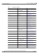
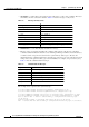
Table 1-1 lists the
switch facility codes.
These messages are described in Chapter 2, “Message and Recovery Procedures,” in alphabetical
order by facility code, with the most severe (lowest number) errors described first.
Ta b l e 1-1 Facility Codes
Facility Code Description Location
ACLMGR ACL manager “ACLMGR Messages” section
on page 2-2
BSPATCH Boot loader patch “BSPATCH Messages” section
on page 2-6