GETTING STARTED GUIDE Cisco Catalyst Blade Switch 3000 Series for HP Getting Started Guide 1 About This Guide 2 Taking Out What You Need 3 HP Blade System Architecture 4 Installing the Switch Module in the Blade Enclosure 5 Using the Onboard Administrator to Assign an IP Address to the Switch Module and Running Express Setup 6 Managing the Switch Module 7 Planning and Creating a Switch Stack (Only the Cisco Catalyst Blade Switch 3120 for HP) 8 Connecting to the Switch Module Ports 9 In Cas
1 About This Guide This guide provides instructions on how to install your Cisco Catalyst Blade Switch 3120 for HP or Cisco Catalyst Blade Switch 3020 for HP— referred to as the switch module—in the HP c-Class BladeSystem and how to set up and configure your switch module. The HP c-Class BladeSystem— referred to as the blade enclosure—supports up to eight Ethernet switch modules, which are installed in the interconnect bays of the blade enclosure.
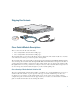
Shipping Box Contents SYST S-MODE S-MSTR S-MMBR UID 19-20 MODE 23x CONSOL E SFP19-2 0 21-22 STK A SFP 21-2 2 24x STK B 26x WS-CBS31 Do cu m CD enta tio n 250286 20G-S Cisco Switch Module Descriptions These sections describe the switch modules: • Cisco Catalyst Blade Switch 3120 for HP, page 3 • Cisco Catalyst Blade Switch 3020 for HP, page 5 The switch module is powered from the blade enclosure backplane. The switch module does not have a fan.
The Cisco Catalyst Blade Switch 3120 for HP has a 3120G and a 3120X model. Both are stacking-capable. The initial setup procedure for both models is the same. For more information about the features of each model, see the hardware installation guide and the software configuration guide for the switch module. Figure 1 shows the Cisco Catalyst Blade Switch 3120 for HP switch module.
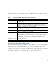
Table 1 describes the Cisco Catalyst Blade Switch 3120 for HP switch module ports. Each external port has an associated LED. Table 1 Cisco Catalyst Blade Switch 3120 for HP Port Descriptions Port Description Ports 1 to 16 Internal Gigabit Ethernet 1000BASE-X downlink ports that connect to the blade enclosure. Ports 17 to 18 Internal cross-connection ports that you can use to connect to a second switch in the blade enclosure through a backplane connector.
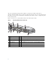
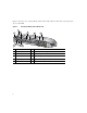
Figure 2 shows the Cisco Catalyst Blade Switch 3020 for HP switch module. Each external port has an associated LED.
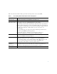
Table 2 describes the switch module ports. Each external port has an associated LED. Table 2 Cisco Catalyst Blade Switch 3020 for HP Port Descriptions Port Description Ports 1 to 16 Internal Gigabit Ethernet 1000BASE-X downlink ports. Ports 17 to 20 and Ports 17x to 20x Dual-purpose SFP module/RJ-45 copper Ethernet uplink ports. The SFP module ports support only Cisco 1000BASE-SX fiber-optic modules. By default, the switch module dynamically selects the interface type that first links up.
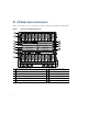
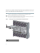
3 HP Blade System Architecture Figure 3 shows the rear view of the blade enclosure, in which you install the switch module.
Consider these prerequisites before you install the switch module: • Fill any unoccupied interconnect bays or any unoccupied power module bays in the blade enclosure with blanks. • Identify the bays in which you will insert the switch modules. Plan to install the first switch module in bay 1, the second in bay 2, and so on up to bay 8, if possible.
Follow these steps to install the switch module in the blade enclosure. The illustrations in this section show the Cisco Catalyst Blade Switch 3020 for HP switch module. The instructions are the same for the Cisco Catalyst Blade Switch 3120 for HP switch module. Step 1 If you have not already done so, touch the static-protective package that contains the switch module to an unpainted metal part of the blade enclosure for at least 2 seconds.
Ensure that the release latch on the switch module is in the open position (perpendicular to the module) Step 4 : SYST STAT DLX SPD UID MODE WS-CB S-3020 CONS -HPQ OLE 17 MEDIA DETECT SFP/R- 45 PORT S 17-20 17x 17x 21 x 20 17 19 20 20x 24 x 23x 18x 153141 18 24x Slide the switch module into the bay until it stops. (See Figure 5.
Step 6 Push the release latch on the front of the switch module to the closed position. 5 Using the Onboard Administrator to Assign an IP Address to the Switch Module and Running Express Setup For the switch module to obtain an IP address for the Fa0 interface through the Onboard Administrator, these conditions must be met: • The blade enclosure is powered on and connected to the network.
Step 4 Using a PC that is connected to the same network segment as the blade enclosure Onboard Administrator, access the Onboard Administrator in a browser window. Enter your assigned user name and password. Step 5 Choose Enclosure Information > Interconnect Bays to open the Interconnect Bay Summary window where you can find the assigned IP address of the switch module Fa0 interface in the Management URL column.
Figure 6 Express Setup Page for the Cisco Catalyst Blade Switch 3120 for HP Figure 7 Express Setup Page for the Cisco Catalyst Blade Switch 3020 for HP Step 8 14 Go to “Using Express Setup” to finish setting up the switch module.
Using Express Setup Before you complete the setup program, obtain the default gateway IP address and the switch password from your system administrator.
Figure 8 Advanced Settings Tab Step 2 In the Host Name field, enter a name for the switch module. The host name is limited to 31 characters; embedded spaces are not allowed. Step 3 In the System Date and System Time fields, enter the current date and time, or use the down arrows to select them. Step 4 In the Time Zone field, use the down arrow to choose your time zone. Step 5 Click Enable in the Daylight Savings Time field to enable this feature.
Step 9 If you enable SNMP, you must enter a community string in the SNMP Read Community field, the SNMP Write Community field, or both. SNMP community strings authenticate access to MIB objects. Embedded spaces are not allowed in SNMP community strings. When you set the SNMP read community, you can access SNMP information, but you cannot modify it. When you set the SNMP write community, you can both access and modify SNMP information.
Step 6 Enter end. Step 7 Enter copy running-configuration startup-configuration to save this setting. Step 8 At the prompt, press Return. Step 9 To verify that this switch is set as the stack master, enter the show switch user EXEC command. For more information about creating switch stacks, see the “Planning and Creating a Switch Stack (Only the Cisco Catalyst Blade Switch 3120 for HP)” section on page 21.
Figure 9 Device Manager Page for the Cisco Catalyst Blade Switch 3120 for HP 19
Figure 10 Device Manager Page for the Cisco Catalyst Blade Switch 3020 for HP Step 3 Use the device manager to perform basic switch module configuration and monitoring. See the device manager online help for more information. Step 4 For more advanced configuration, download and run the Cisco Network Assistant, which is described in the next section. Using the Command-Line Interface You can enter Cisco IOS commands and parameters through the CLI.
Step 3 Configure the PC terminal emulation software for: – 9600 baud – 8 data bits – No parity – 1 stop bit – No flow control Step 4 Use the CLI to enter commands to configure the switch module. See the software configuration guide and the command reference for more information. Using the Onboard Administrator CLI See the HP BladeSystem enclosure setup and installation guide at http://www.hp.com/go/bladesystem/documentation for information on how to use the Onboard Administration CLI.
Caution The Cisco Catalyst Blade Switch 3120 for HP switch modules do not support switch stacks with other types of blades switches as members. Combining the Cisco Catalyst Blade Switch 3120 for HP with other types of blade switches in a switch stack might cause the switch to work improperly or to fail. When switch modules are not stacked, each acts as a standalone switch. For general concepts and procedures to manage switch stacks, see the switch module software configuration guide and command reference.
To create a switch stack: Step 1 Install the member switch modules if you have not already done so. Step 2 Connect the StackWise Plus cables as described in the “Planning and Creating a Switch Stack (Only the Cisco Catalyst Blade Switch 3120 for HP)” section on page 21. Step 3 Configure the member switch modules through the master switch by using the CLI. Stack Cabling Configurations 250303 This example shows a single chassis with two switches that create one stack.
Figure 11 UID 19-20 MODE 23x CONS OLE SFP19-2 0 21-22 STK A SFP 21 -22 24x STK B 26x WS-CBS3 250302 SYST S-MODE S-MSTR S-MMBR Inserting the StackWise Plus Cables 120G-S When you remove the StackWise Plus cables from the connectors, replace the dust covers to protect them from dust. Caution Removing and installing the StackWise Plus cable can shorten its useful life. Do not remove and insert the cable more often than is absolutely necessary.
For simplified cabling, the automatic medium-dependent interface crossover (auto-MDIX) feature is enabled by default on the switch. With auto-MDIX enabled, the switch detects the required cable type for copper Ethernet connections and configures the interface accordingly. Therefore, you can use either a crossover or a straight-through cable for connections to a switch 10/100/1000 Ethernet port, regardless of the type of device on the other end of the connection.
be turned on, there might be a cable problem, or there might be a problem with the adapter installed in the device. See the “In Case of Difficulty” section on page 26 for information about online assistance. 9 In Case of Difficulty If you experience difficulty, help is available in this section and also on Cisco.com. This section includes how to reset the switch module, how to access online help, and where to find more information.
For More Information For more information about the switch module, see these documents on Cisco.com: • Cisco Catalyst Blade Switch 3120 for HP Hardware Installation Guide and Cisco Catalyst Blade Switch 3020 for HP Hardware Installation Guide (not orderable, but available on Cisco.com). This guide provides complete hardware descriptions and detailed installation procedures.
Americas Headquarters Cisco Systems, Inc. 170 West Tasman Drive San Jose, CA 95134-1706 USA www.cisco.com Tel: 408 526-4000 800 553-NETS (6387) Fax: 408 527-0883 Asia Pacific Headquarters Cisco Systems, Inc. 168 Robinson Road #28-01 Capital Tower Singapore 068912 www.cisco.com Tel: +65 6317 7777 Fax: +65 6317 7799 Europe Headquarters Cisco Systems International BV Haarlerbergpark Haarlerbergweg 13-19 1101 CH Amsterdam The Netherlands www-europe.cisco.