
Cisco Catalyst Blade Switch 3020 for HP Software Configuration Guide, Rel. 12.2(25)SEF1


10-22
Cisco Catalyst Blade Switch 3020 for HP Software Configuration Guide
OL-8915-01
Chapter 10 Configuring VLANs
Configuring VLAN Trunks
You configure load sharing on trunk ports by using STP port priorities or STP path costs. For load
sharing using STP port priorities, both load-sharing links must be connected to the same switch. For load
sharing using STP path costs, each load-sharing link can be connected to the same switch or to two
different switches. For more information about STP, see Chapter 13, “Configuring STP.”
Load Sharing Using STP Port Priorities
When two ports on the same switch form a loop, the switch uses the STP port priority to decide which
port is enabled and which port is in a blocking state. You can set the priorities on a parallel trunk port so
that the port carries all the traffic for a given VLAN. The trunk port with the higher priority (lower
values) for a VLAN is forwarding traffic for that VLAN. The trunk port with the lower priority (higher
values) for the same VLAN remains in a blocking state for that VLAN. One trunk port sends or receives
all traffic for the VLAN.
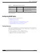
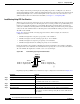
Figure 10-3 shows two trunks connecting supported switches. In this example, the switches are
configured as follows:
• VLANs 8 through 10 are assigned a port priority of 16 on Trunk 1.
• VLANs 3 through 6 retain the default port priority of 128 on Trunk 1.
• VLANs 3 through 6 are assigned a port priority of 16 on Trunk 2.
• VLANs 8 through 10 retain the default port priority of 128 on Trunk 2.
In this way, Trunk 1 carries traffic for VLANs 8 through 10, and Trunk 2 carries traffic for VLANs 3
through 6. If the active trunk fails, the trunk with the lower priority takes over and carries the traffic for
all of the VLANs. No duplication of traffic occurs over any trunk port.
Figure 10-3 Load Sharing by Using STP Port Priorities
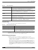
Beginning in privileged EXEC mode, follow these steps to configure the network shown in Figure 10-3.
93370
Switch A
Switch B
Trunk 2
VLANs 3 – 6 (priority 16)
VLANs 8 – 10 (priority 128)
Trunk 1
VLANs 8 – 10 (priority 16)
VLANs 3 – 6 (priority 128)
Command Purpose
Step 1
configure terminal Enter global configuration mode on Switch A.
Step 2
vtp domain domain-name Configure a VTP administrative domain.
The domain name can be 1 to 32 characters.
Step 3
vtp mode server Configure Switch A as the VTP server.
Step 4
end Return to privileged EXEC mode.
Step 5
show vtp status Verify the VTP configuration on both Switch A and Switch B.
In the display, check the VTP Operating Mode and the VTP Domain
Name fields.