Se n d d o c u m e n t a t i o n c o m m e n t s t o m d s f e e d b a ck - d o c @ c i s c o . c o m Cisco MDS 9100 Series Hardware Installation Guide February 2008 Americas Headquarters Cisco Systems, Inc. 170 West Tasman Drive San Jose, CA 95134-1706 USA http://www.cisco.
Se n d d o c u m e n t a t i o n c o m m e n t s t o m d s f e e d b a ck - d o c @ c i s c o . c o m THE SPECIFICATIONS AND INFORMATION REGARDING THE PRODUCTS IN THIS MANUAL ARE SUBJECT TO CHANGE WITHOUT NOTICE. ALL STATEMENTS, INFORMATION, AND RECOMMENDATIONS IN THIS MANUAL ARE BELIEVED TO BE ACCURATE BUT ARE PRESENTED WITHOUT WARRANTY OF ANY KIND, EXPRESS OR IMPLIED. USERS MUST TAKE FULL RESPONSIBILITY FOR THEIR APPLICATION OF ANY PRODUCTS.
Se n d d o c u m e n t a t i o n c o m m e n t s t o m d s f e e d b a ck - d o c @ c i s c o .
Contents Se n d d o c u m e n t a t i o n c o m m e n t s t o m d s f e e d b a ck - d o c @ c i s c o .
Contents Se n d d o c u m e n t a t i o n c o m m e n t s t o m d s f e e d b a ck - d o c @ c i s c o .
Contents Se n d d o c u m e n t a t i o n c o m m e n t s t o m d s f e e d b a ck - d o c @ c i s c o .
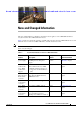
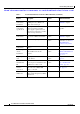
Se n d d o c u m e n t a t i o n c o m m e n t s t o m d s f e e d b a ck - d o c @ c i s c o . c o m New and Changed Information This Cisco MDS 9100 Series Hardware Installation Guide applies to Cisco MDS NX-OS Release 4.1(1b) and earlier Cisco MDS SAN-OS releases. Table 1 lists the new and changed features available with each supported Cisco MDS NX-OS release and SAN-OS release for the Cisco MDS 9100 Series, with the latest release first. Note As of NX-OS Release 4.
New and Changed Information Se n d d o c u m e n t a t i o n c o m m e n t s t o m d s f e e d b a ck - d o c @ c i s c o . c o m Table 1 Documented Features for the Cisco MDS 9100 Series (continued) Changed in Release Feature Description Cisco MDS 9134 Switch installation Description and illustrations of installing the Cisco MDS 9134 Switch and removing it. Cisco MDS 9134 Switch specifications Switch specifications for the Cisco 3.
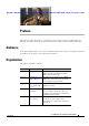
Se n d d o c u m e n t a t i o n c o m m e n t s t o m d s f e e d b a ck - d o c @ c i s c o . c o m Preface This preface describes the audience, organization, and conventions of the Cisco MDS 9100 Series Hardware Installation Guide. It also provides information on how to obtain related documentation. Audience To use this installation guide, you need to be familiar with electronic circuitry and wiring practices and preferably be an electronic or electromechanical technician.
Preface Se n d d o c u m e n t a t i o n c o m m e n t s t o m d s f e e d b a ck - d o c @ c i s c o . c o m Chapter Title Description Appendix C Cable and Port Specifications Lists cable and port specifications for the Cisco MDS 9100 Series switch. Appendix D Site Planning and Maintenance Records Provides site planning and maintenance records. Document Conventions Notes use the following conventions: Note Means reader take note.
Preface Se n d d o c u m e n t a t i o n c o m m e n t s t o m d s f e e d b a ck - d o c @ c i s c o . c o m Attention Ce symbole d'avertissement indique un danger. Vous vous trouvez dans une situation pouvant causer des blessures ou des dommages corporels. Avant de travailler sur un équipement, soyez conscient des dangers posés par les circuits électriques et familiarisez-vous avec les procédures couramment utilisées pour éviter les accidents.
Preface Se n d d o c u m e n t a t i o n c o m m e n t s t o m d s f e e d b a ck - d o c @ c i s c o . c o m Varning! Denna varningssymbol signalerar fara. Du befinner dig i en situation som kan leda till personskada. Innan du utför arbete på någon utrustning måste du vara medveten om farorna med elkretsar och känna till vanligt förfarande för att förebygga skador.
Preface Se n d d o c u m e n t a t i o n c o m m e n t s t o m d s f e e d b a ck - d o c @ c i s c o .
Preface Se n d d o c u m e n t a t i o n c o m m e n t s t o m d s f e e d b a ck - d o c @ c i s c o . c o m Obtaining Documentation, Obtaining Support, and Security Guidelines For information on obtaining documentation, submitting a service request, and gathering additional information, see the monthly What’s New in Cisco Product Documentation, which also lists all new and revised Cisco technical documentation, at: http://www.cisco.com/en/US/docs/general/whatsnew/whatsnew.
Se n d d o c u m e n t a t i o n c o m m e n t s t o m d s f e e d b a ck - d o c @ c i s c o . c o m CH A P T E R 1 Product Overview The Cisco MDS 9100 Series Multilayer Fabric Switches provide an intelligent, cost-effective, and small-profile switching platform for small- and medium-sized storage environments.
Chapter 1 Product Overview Cisco MDS 9100 Series Multilayer Fabric Switches Se n d d o c u m e n t a t i o n c o m m e n t s t o m d s f e e d b a ck - d o c @ c i s c o . c o m The Cisco MDS 9134 Multilayer Fabric Switch and the Cisco MDS 9124 Multilayer Fabric Switch also provide the following features: • On-Demand Port activation licensing that provides 8-, 16-, and 24-port configurations in the Cisco MDS 9124 Switch to optimize price and scalability.
Chapter 1 Product Overview Cisco MDS 9100 Series Multilayer Fabric Switches Se n d d o c u m e n t a t i o n c o m m e n t s t o m d s f e e d b a ck - d o c @ c i s c o . c o m Cisco MDS 9134 Switch The Cisco MDS 9134 Multilayer Fabric Switch has a total of 32 1-, 2-, and 4-Gbps autosensing Fibre Channel ports, and 2 10-Gbps ports. The Cisco MDS 9134 Switch (see Figure 1-1) features On-Demand Port activation licensing. By default, the first 24 ports are licensed.
Chapter 1 Product Overview Cisco MDS 9100 Series Multilayer Fabric Switches Se n d d o c u m e n t a t i o n c o m m e n t s t o m d s f e e d b a ck - d o c @ c i s c o . c o m Cisco MDS 9124 Switch The Cisco MDS 9124 Multilayer Fabric Switch has a total of 24 1-, 2-, and 4-Gbps autosensing Fibre Channel ports. The Cisco MDS 9124 Switch features On-Demand Port Licensing. You can activate licensing in 8-port increments with each on-demand port activation license for up to a total of 24 ports.
Chapter 1 Product Overview Cisco MDS Fibre Channel Bladeswitch for IBM BladeCenter Se n d d o c u m e n t a t i o n c o m m e n t s t o m d s f e e d b a ck - d o c @ c i s c o . c o m Cisco MDS 9120 Switch The Cisco MDS 9120 Switch has a total of 20 1/2-Gbps autosensing, optionally configurable ports. The first group of four ports on the left-hand side are the bandwidth-optimized ports. They are delineated by a white border.
Chapter 1 Product Overview Power Supplies Se n d d o c u m e n t a t i o n c o m m e n t s t o m d s f e e d b a ck - d o c @ c i s c o . c o m Power Supplies The Cisco MDS 9100 Series supports dual AC and DC power supplies. Each power supply provides sufficient power to maintain switch operation in the event of a single power supply failure. Power supplies are hot swappable and can be individually replaced without disruption to the system. (See the “Power Specifications” section on page B-2.
Chapter 1 Product Overview Cisco MDS 9100 Series Ports Se n d d o c u m e n t a t i o n c o m m e n t s t o m d s f e e d b a ck - d o c @ c i s c o . c o m Caution The Cisco MDS 9000 Family has internal temperature sensors that are capable of shutting down the system if the temperature at different points within the chassis exceed certain safety thresholds.
Chapter 1 Product Overview Cisco MDS 9100 Series Ports Se n d d o c u m e n t a t i o n c o m m e n t s t o m d s f e e d b a ck - d o c @ c i s c o . c o m All 32 4-Gbps ports and 2 10-Gbps ports can operate at line rate concurrently. In addition, the 10-Gbps ports can be activated independently at 24- or 32-port configurations. A 64-port switch can be formed by stacking two Cisco MDS 9134 Switches together using a copper CX4 X2 transceiver.
Chapter 1 Product Overview Cisco MDS 9100 Series Ports Se n d d o c u m e n t a t i o n c o m m e n t s t o m d s f e e d b a ck - d o c @ c i s c o . c o m Ports on the Cisco MDS 9124 Switch The Cisco MDS 9124 Switch has 24 1-, 2-, and 4-Gbps autosensing and autonegotiating Fibre Channel ports with on-demand port activation licensing. The on-demand ports are licensed in groups of eight. By default, an on-demand license for the first eight ports (ports 1 through 8) is included with the switch.
Chapter 1 Product Overview Switch LEDs Se n d d o c u m e n t a t i o n c o m m e n t s t o m d s f e e d b a ck - d o c @ c i s c o . c o m Only the first port in each four-port group can be an Inter-Switch Link (ISL). If the first port is an ISL, the other three ports in the group are disabled. See Figure 1-8.
Chapter 1 Product Overview Switch LEDs Se n d d o c u m e n t a t i o n c o m m e n t s t o m d s f e e d b a ck - d o c @ c i s c o .
Chapter 1 Product Overview Switch LEDs Se n d d o c u m e n t a t i o n c o m m e n t s t o m d s f e e d b a ck - d o c @ c i s c o . c o m Table 1-2 describes the front panel LEDs for the Cisco MDS 9100 Series. Table 1-2 Switching Module LEDs LED Status Description Switch status Green All diagnostics pass. The module is operational (normal initialization sequence). Orange The module is booting or running diagnostics (normal initialization sequence). Switch temperature is high.
Chapter 1 Product Overview Supported SFP Transceivers Se n d d o c u m e n t a t i o n c o m m e n t s t o m d s f e e d b a ck - d o c @ c i s c o .
Chapter 1 Product Overview Supported SFP Transceivers Se n d d o c u m e n t a t i o n c o m m e n t s t o m d s f e e d b a ck - d o c @ c i s c o . c o m Combination Fibre Channel/Gigabit Ethernet SFP Transceivers The combination Fibre Channel/Gigabit Ethernet SFP transceivers from Cisco Systems are available in SWL or LWL versions for the Cisco MDS 9140 Switch and the Cisco MDS 9120 Switch. Both versions are 1-Gbps and 2-Gbps capable.
Se n d d o c u m e n t a t i o n c o m m e n t s t o m d s f e e d b a ck - d o c @ c i s c o .
Chapter 2 Installing the Cisco MDS 9100 Series Preinstallation Se n d d o c u m e n t a t i o n c o m m e n t s t o m d s f e e d b a ck - d o c @ c i s c o . c o m Warning IMPORTANT SAFETY INSTRUCTIONS This warning symbol means danger. You are in a situation that could cause bodily injury. Before you work on any equipment, be aware of the hazards involved with electrical circuitry and be familiar with standard practices for preventing accidents.
Chapter 2 Installing the Cisco MDS 9100 Series Preinstallation Se n d d o c u m e n t a t i o n c o m m e n t s t o m d s f e e d b a ck - d o c @ c i s c o . c o m • In a two-post telco rack, using: – The telco and EIA Shelf Bracket Kit (an optional kit, purchased separately) in addition to the front brackets shipped with the switch For instructions on installing the switch using the rack-mount kit shipped with the switch, see the“Installing the Switch in a Cabinet or Rack” section on page 2-5.
Chapter 2 Installing the Cisco MDS 9100 Series Preinstallation Se n d d o c u m e n t a t i o n c o m m e n t s t o m d s f e e d b a ck - d o c @ c i s c o . c o m • Ensure that circuits are sized according to local and national codes. For North America, the 300-W power supplies require a 20-A circuit. If you are using a 200- or 240-VAC power source in North America, the circuit must be protected by a two-pole circuit breaker.
Chapter 2 Installing the Cisco MDS 9100 Series Installing the Switch in a Cabinet or Rack Se n d d o c u m e n t a t i o n c o m m e n t s t o m d s f e e d b a ck - d o c @ c i s c o . c o m Tip Keep the shipping container in case the chassis requires shipping in the future. Note If you purchased Cisco support through a Cisco reseller, contact the reseller directly. If you purchased support directly from Cisco, contact Cisco Technical Support at this URL: http://www.cisco.
Chapter 2 Installing the Cisco MDS 9100 Series Installing the Switch in a Cabinet or Rack Se n d d o c u m e n t a t i o n c o m m e n t s t o m d s f e e d b a ck - d o c @ c i s c o . c o m The rack-mount kit provided with the switch contains the items listed in Table 2-1.
Chapter 2 Installing the Cisco MDS 9100 Series Installing the Switch in a Cabinet or Rack Se n d d o c u m e n t a t i o n c o m m e n t s t o m d s f e e d b a ck - d o c @ c i s c o . c o m Figure 2-1 Front Rack-Mount Brackets and C Brackets Installed on the Cisco MDS 9100 Series 96616 2 1 1 Step 3 2 C bracket Install the slider rails in the rack. Position one of the slider rails against the rack mounting rails and align the screw holes as shown in Figure 2-2.
Chapter 2 Installing the Cisco MDS 9100 Series Installing the Switch in a Cabinet or Rack Se n d d o c u m e n t a t i o n c o m m e n t s t o m d s f e e d b a ck - d o c @ c i s c o . c o m b. Use the tape measure and level to verify that the rails are horizontal and at the same height.
Chapter 2 Installing the Cisco MDS 9100 Series Installing the Switch in a Cabinet or Rack Se n d d o c u m e n t a t i o n c o m m e n t s t o m d s f e e d b a ck - d o c @ c i s c o . c o m Step 5 Insert the switch into the rack: a. By using both hands, position the switch with the back of the switch between the front rack-mounting rails as shown in Figure 2-4. If you are using the notched rails, for the Cisco MDS 9134 Switch or the Cisco MDS 9124 Switch, see Figure 2-5. b.
Chapter 2 Installing the Cisco MDS 9100 Series Installing the Switch in a Cabinet or Rack Se n d d o c u m e n t a t i o n c o m m e n t s t o m d s f e e d b a ck - d o c @ c i s c o . c o m Sliding the Cisco MDS 9134 Switch or the Cisco MDS 9124 Switch onto the Notched Slider Rails 182460 Figure 2-5 Step 6 Stabilize the switch in the rack by attaching the front rack-mount brackets to the front rack-mounting rails: a.
Chapter 2 Installing the Cisco MDS 9100 Series Installing the Switch in a Cabinet with Insufficient Front Clearance Se n d d o c u m e n t a t i o n c o m m e n t s t o m d s f e e d b a ck - d o c @ c i s c o .
Chapter 2 Installing the Cisco MDS 9100 Series Installing the Switch in a Cabinet with Insufficient Front Clearance Se n d d o c u m e n t a t i o n c o m m e n t s t o m d s f e e d b a ck - d o c @ c i s c o . c o m less than three-inch clearance between the inside of the front door or bezel panel and the front cabinet mounting rails. This rear-facing installation is necessary to ensure that the minimum bend radius for the fiber-optic cables is maintained.
Chapter 2 Installing the Cisco MDS 9100 Series Installing the Switch in a Cabinet with Insufficient Front Clearance Se n d d o c u m e n t a t i o n c o m m e n t s t o m d s f e e d b a ck - d o c @ c i s c o . c o m Installing Front Rack-Mount Brackets for Cabinets with 26 Inches or Greater of Rail Spacings The front rack-mount brackets for the Cisco MDS 9100 Series switch must be installed onto the switch prior to installing the switch into the cabinet.
Chapter 2 Installing the Cisco MDS 9100 Series Installing the Switch in a Cabinet with Insufficient Front Clearance Se n d d o c u m e n t a t i o n c o m m e n t s t o m d s f e e d b a ck - d o c @ c i s c o . c o m Installing Front Rack-Mount Brackets for Cabinets with Less Than 26 Inches of Rail Spacings The front rack-mount brackets for the Cisco MDS 9100 Series switches must be installed onto the switch prior to installing the switch into the cabinet.
Chapter 2 Installing the Cisco MDS 9100 Series Installing the Switch in a Cabinet with Insufficient Front Clearance Se n d d o c u m e n t a t i o n c o m m e n t s t o m d s f e e d b a ck - d o c @ c i s c o .
Chapter 2 Installing the Cisco MDS 9100 Series Installing the Switch in a Cabinet with Insufficient Front Clearance Se n d d o c u m e n t a t i o n c o m m e n t s t o m d s f e e d b a ck - d o c @ c i s c o . c o m Step 2 Insert the switch into the rack: a. Note By using both hands, position the switch with the back of the switch between the rear rack-mounting rails as shown in Figure 2-11. Figure 2-11 shows the front rack-mount brackets in a 180 degree position.
Chapter 2 Installing the Cisco MDS 9100 Series Installing the Switch in a Cabinet with Insufficient Front Clearance Se n d d o c u m e n t a t i o n c o m m e n t s t o m d s f e e d b a ck - d o c @ c i s c o . c o m Figure 2-12 Attaching the Cisco MDS 9100 Series Switch (Rear-Facing) to the Cabinet Rear cabinet mounting rails b. 113430 Front cabinet mounting rails Repeat for the front rack-mount bracket on the other side of the switch.
Chapter 2 Installing the Cisco MDS 9100 Series Installing the Switch in a Cabinet with Insufficient Front Clearance Se n d d o c u m e n t a t i o n c o m m e n t s t o m d s f e e d b a ck - d o c @ c i s c o . c o m Note When installing the Cisco MDS 9134 Switch or the Cisco MDS 9124 Switch rear-facing into a cabinet, do not install it higher than RU-30. a.
Chapter 2 Installing the Cisco MDS 9100 Series Installing the Switch in a Cabinet with Insufficient Front Clearance Se n d d o c u m e n t a t i o n c o m m e n t s t o m d s f e e d b a ck - d o c @ c i s c o . c o m Step 2 Insert the switch into the rack: a. Using both hands, position the switch with the back of the switch between the rear rack-mounting rails as shown in Figure 2-14.
Chapter 2 Installing the Cisco MDS 9100 Series Installing the Switch in a Cabinet with Insufficient Front Clearance Se n d d o c u m e n t a t i o n c o m m e n t s t o m d s f e e d b a ck - d o c @ c i s c o .
Chapter 2 Installing the Cisco MDS 9100 Series Installing Cisco MDS 9134 48-Port and 64-Port Stackable Bundles Se n d d o c u m e n t a t i o n c o m m e n t s t o m d s f e e d b a ck - d o c @ c i s c o . c o m Step 4 Stabilize the switch in the rack by attaching the front rack-mount brackets to the rear rack-mounting rails: a.
Chapter 2 Installing the Cisco MDS 9100 Series Installing Cisco MDS 9134 48-Port and 64-Port Stackable Bundles Se n d d o c u m e n t a t i o n c o m m e n t s t o m d s f e e d b a ck - d o c @ c i s c o . c o m Step 2 Install two MDS 9134 Switches placing one on top of the other (recommended) or side-by-side. In a stacked switch configuration, the distance between the 10-Gbps ports of the two switches can be maximum of 1 meter. Currently, only one-meter cables are shipped with the boxes.
Chapter 2 Installing the Cisco MDS 9100 Series Grounding the Switch Se n d d o c u m e n t a t i o n c o m m e n t s t o m d s f e e d b a ck - d o c @ c i s c o . c o m Grounding the Switch A grounding pad with two threaded M4 holes is provided on the chassis for attaching a grounding lug. Figure 2-19 shows the system ground location on the Cisco MDS 9100 Series.
Chapter 2 Installing the Cisco MDS 9100 Series Starting Up the Switch Se n d d o c u m e n t a t i o n c o m m e n t s t o m d s f e e d b a ck - d o c @ c i s c o . c o m Note Customers who require compliance to GR-1089-CORE bonding and grounding requirements, must use the ground conductor. To attach the grounding lug and cable to the chassis, follow these steps: Step 1 Use a wire-stripping tool to remove approximately 0.75 in. (19 mm) of the covering from the end of the grounding cable.
Chapter 2 Installing the Cisco MDS 9100 Series Starting Up the Switch Se n d d o c u m e n t a t i o n c o m m e n t s t o m d s f e e d b a ck - d o c @ c i s c o . c o m Step 4 Ensure that the switch is adequately grounded as described in the “Installing the Switch in a Cabinet with Insufficient Front Clearance” section on page 2-11, and that the power cables are connected to outlets that have the required AC power voltages (provided in the “Power Specifications” section on page B-2).
Chapter 2 Installing the Cisco MDS 9100 Series Removing and Installing Components Se n d d o c u m e n t a t i o n c o m m e n t s t o m d s f e e d b a ck - d o c @ c i s c o . c o m Removing and Installing Components The Cisco MDS 9140 Switch and the Cisco MDS 9120 Switch is shipped with two field-replaceable power supplies. Each power supply includes a fixed fan. The Cisco MDS 9140 Switch and the Cisco MDS 9120 Switch also have two field-replaceable fan modules.
Chapter 2 Installing the Cisco MDS 9100 Series Removing and Installing Components Se n d d o c u m e n t a t i o n c o m m e n t s t o m d s f e e d b a ck - d o c @ c i s c o .
Chapter 2 Installing the Cisco MDS 9100 Series Removing and Installing Components Se n d d o c u m e n t a t i o n c o m m e n t s t o m d s f e e d b a ck - d o c @ c i s c o . c o m For the Cisco MDS 9140 Switch and the Cisco MDS 9120 Switch, the fans should not be removed for prolonged periods of time during operation.
Chapter 2 Installing the Cisco MDS 9100 Series Removing and Installing Components Se n d d o c u m e n t a t i o n c o m m e n t s t o m d s f e e d b a ck - d o c @ c i s c o . c o m Cisco MDS 9100 Series AC Power Supply AC OK DC OK 94008 Figure 2-23 Installing Power Supplies To install the dual 300-W AC-input power supplies, follow these steps: Step 1 Ensure that the system (earth) ground connection has been made. Step 2 Make sure the power cord is disconnected before installing the power supply.
Chapter 2 Installing the Cisco MDS 9100 Series Removing and Installing Components Se n d d o c u m e n t a t i o n c o m m e n t s t o m d s f e e d b a ck - d o c @ c i s c o . c o m Removing and Installing DC Power Supplies This section provides instructions for removing and installing the DC power supplies for the Cisco MDS 9100 Series switch. Note Caution The new DC power supply is not supported on the Cisco MDS 9140 Switch and the Cisco MDS 9120 Switch.
Chapter 2 Installing the Cisco MDS 9100 Series Removing and Installing Components Se n d d o c u m e n t a t i o n c o m m e n t s t o m d s f e e d b a ck - d o c @ c i s c o . c o m Figure 2-24 Cisco MDS 9100 Series DC Power Supply DC input terminals Status LEDs 120697 Handle Installing Power Supplies To install the 300-W DC-input power supplies, follow these steps: Step 1 Ensure that the system (earth) ground connection has been made. Step 2 Slide the power supply into the power supply bay.
Chapter 2 Installing the Cisco MDS 9100 Series Removing and Installing Components Se n d d o c u m e n t a t i o n c o m m e n t s t o m d s f e e d b a ck - d o c @ c i s c o . c o m Removing and Installing Fan Modules This section provides instructions for removing and installing the fan modules for the Cisco MDS 9140 Switch and the Cisco MDS 9120 Switch. The Cisco MDS 9124 Switch does not have field-replaceable fan modules.
Chapter 2 Installing the Cisco MDS 9100 Series Removing and Installing Components Se n d d o c u m e n t a t i o n c o m m e n t s t o m d s f e e d b a ck - d o c @ c i s c o . c o m Installing a Fan Module To install a new fan module, follow these steps: Step 1 Position the fan module with the LED oriented away from the back of the switch. Figure 2-25 shows the fan module for the Cisco MDS 9120 Switch and the Cisco MDS 9140 Switch. Figure 2-26 shows the fan module for the Cisco MDS 9134 Switch.
Chapter 2 Installing the Cisco MDS 9100 Series Removing and Installing Components Se n d d o c u m e n t a t i o n c o m m e n t s t o m d s f e e d b a ck - d o c @ c i s c o . c o m Verifying the Fan Module To verify that the new fan module is installed correctly, follow these steps: Step 1 Listen for the fans; you should immediately hear them operating. If you do not hear them, ensure that the fan module is inserted completely in the switch and the faceplate is flush with the switch back panel.
Se n d d o c u m e n t a t i o n c o m m e n t s t o m d s f e e d b a ck - d o c @ c i s c o . c o m CH A P T E R 3 Connecting the Cisco MDS 9100 Series The Cisco MDS 9100 Series provides the following types of ports: • Console port (Interface Module)—An RS-232 port that you can use to create a local management connection. • MGMT 10/100 Ethernet port (Interface Module)—An Ethernet port that you can use to access and manage the switch by IP address, such as through the CLI or Fabric Manager.
Chapter 3 Connecting the Cisco MDS 9100 Series Connecting the Console Port Se n d d o c u m e n t a t i o n c o m m e n t s t o m d s f e e d b a ck - d o c @ c i s c o . c o m • Download software updates to the switch or distribute software images residing in flash memory to attached devices. The console port, located on the front panel, is shown in Figure 3-1.
Chapter 3 Connecting the Cisco MDS 9100 Series Connecting the 10/100 Ethernet Management Port Se n d d o c u m e n t a t i o n c o m m e n t s t o m d s f e e d b a ck - d o c @ c i s c o . c o m Connecting a Modem to a Console Port Caution Do not connect the console port to a modem while the switch is booting. Connect the console port to a modem either before powering the switch on or after the switch has completed the boot process. Switches running Cisco MDS SAN-OS Release 1.
Chapter 3 Connecting the Cisco MDS 9100 Series Connecting to a Fibre Channel Port Se n d d o c u m e n t a t i o n c o m m e n t s t o m d s f e e d b a ck - d o c @ c i s c o . c o m Connecting to a Fibre Channel Port The Fibre Channel ports are compatible with LC-type fiber-optic SFP transceivers and cables (see “Removing and Installing Cables into SFP Transceivers” section on page 3-7). You can use these ports to connect to the SAN or for in-band management.
Chapter 3 Connecting the Cisco MDS 9100 Series Connecting to a Fibre Channel Port Se n d d o c u m e n t a t i o n c o m m e n t s t o m d s f e e d b a ck - d o c @ c i s c o .
Chapter 3 Connecting the Cisco MDS 9100 Series Connecting to a Fibre Channel Port Se n d d o c u m e n t a t i o n c o m m e n t s t o m d s f e e d b a ck - d o c @ c i s c o . c o m Removing an SFP Transceiver To remove an SFP transceiver, follow these steps: Step 1 Attach an ESD-preventive wrist strap and follow its instructions for use. Step 2 Perform these steps if cable is installed in the transceiver: a. Record the cable and port connections for later reference. b.
Chapter 3 Connecting the Cisco MDS 9100 Series Connecting to a Fibre Channel Port Se n d d o c u m e n t a t i o n c o m m e n t s t o m d s f e e d b a ck - d o c @ c i s c o . c o m Alternate Removal Method for Bale Clasp SFP Transceivers in the Cisco MDS 9140 Switch and the Cisco MDS 9120 Switch 115237 Figure 3-5 Step 4 Insert a dust cover into the port end of the transceiver and place the transceiver on an antistatic mat or into a static shielding bag if you plan to return it to the factory.
Chapter 3 Connecting the Cisco MDS 9100 Series Connecting to a Fibre Channel Port Se n d d o c u m e n t a t i o n c o m m e n t s t o m d s f e e d b a ck - d o c @ c i s c o . c o m Figure 3-6 Connecting the LC-Type Cable to a Fibre Channel Port LC plug 91681 SFP module Caution If the cable does not install easily, ensure it is correctly oriented before continuing.
Chapter 3 Connecting the Cisco MDS 9100 Series Connecting to a Fibre Channel Port Se n d d o c u m e n t a t i o n c o m m e n t s t o m d s f e e d b a ck - d o c @ c i s c o . c o m Maintaining SFP Transceivers and Fiber-Optic Cables SFP transceivers and fiber-optic cables must be kept clean and dust-free to maintain high signal accuracy and prevent damage to the connectors. Attenuation (loss of light) is increased by contamination, and it should be kept below 0.35 dB.
Chapter 3 Connecting the Cisco MDS 9100 Series Connecting to a Fibre Channel Port Se n d d o c u m e n t a t i o n c o m m e n t s t o m d s f e e d b a ck - d o c @ c i s c o .
Se n d d o c u m e n t a t i o n c o m m e n t s t o m d s f e e d b a ck - d o c @ c i s c o .
Appendix A Cabinet and Rack Installation Cabinet and Rack Requirements Se n d d o c u m e n t a t i o n c o m m e n t s t o m d s f e e d b a ck - d o c @ c i s c o . c o m • For four-post EIA cabinets (perforated or solid-walled): – The minimum spacing for bend radius for fiber-optic cables should have the front mounting rails of the cabinet offset from the front door by a minimum of 3 in. (7.6 cm), and a minimum of 5 in. (12.
Appendix A Cabinet and Rack Installation Cisco MDS 9000 Family Telco and EIA Shelf Bracket Se n d d o c u m e n t a t i o n c o m m e n t s t o m d s f e e d b a ck - d o c @ c i s c o .
Appendix A Cabinet and Rack Installation Cisco MDS 9000 Family Telco and EIA Shelf Bracket Se n d d o c u m e n t a t i o n c o m m e n t s t o m d s f e e d b a ck - d o c @ c i s c o . c o m Note This optional kit is not provided with the switch; to order the kit, contact your switch supplier. This section describes the procedure for installing a Cisco MDS 9000 Family switch in a rack or cabinet using the optional telco and EIA Shelf Bracket Kit.
Appendix A Cabinet and Rack Installation Cisco MDS 9000 Family Telco and EIA Shelf Bracket Se n d d o c u m e n t a t i o n c o m m e n t s t o m d s f e e d b a ck - d o c @ c i s c o . c o m Before Installing the Shelf Brackets Before installing the shelf brackets, inspect the contents of your kit. Table A-1 lists the contents of the shelf bracket kit. Table A-1 Contents of Shelf Bracket Kit Quantity Part Description 2 Slider brackets 2 Shelf brackets 1 Crossbar 2 10-32 x 3/8-in.
Appendix A Cabinet and Rack Installation Cisco MDS 9000 Family Telco and EIA Shelf Bracket Se n d d o c u m e n t a t i o n c o m m e n t s t o m d s f e e d b a ck - d o c @ c i s c o . c o m To install the shelf brackets in a telco rack, follow these steps: Step 1 Position a shelf bracket inside a rack-mounting rail as shown in Figure A-1 and align the screw holes at the front of the shelf bracket with the holes in the rack-mounting rail.
Appendix A Cabinet and Rack Installation Cisco MDS 9000 Family Telco and EIA Shelf Bracket Se n d d o c u m e n t a t i o n c o m m e n t s t o m d s f e e d b a ck - d o c @ c i s c o . c o m Installing the Shelf Bracket Kit into a Four-Post EIA Rack Figure A-2 shows the installation of the shelf bracket kit into a four-post EIA rack.
Appendix A Cabinet and Rack Installation Cisco MDS 9000 Family Telco and EIA Shelf Bracket Se n d d o c u m e n t a t i o n c o m m e n t s t o m d s f e e d b a ck - d o c @ c i s c o . c o m Step 4 Attach the crossbar to the shelf brackets as shown in Figure A-2, using the 10-32 screws. Step 5 Insert the slider rails into the shelf brackets as shown in Figure A-2. Then attach them to the rear rack-mounting rails using a minimum of four 12-24 or 10-24 screws.
Appendix A Cabinet and Rack Installation Cisco MDS 9000 Family Telco and EIA Shelf Bracket Se n d d o c u m e n t a t i o n c o m m e n t s t o m d s f e e d b a ck - d o c @ c i s c o . c o m Removing the Shelf Bracket Kit (Optional) The shelf bracket kit can be removed once the Cisco MDS 9100 Series switch has been installed in a four-post EIA rack, and both front rack-mount brackets and both C brackets are securely attached to the rack-mounting rails.
Appendix A Cabinet and Rack Installation Cisco MDS 9000 Family Telco and EIA Shelf Bracket Se n d d o c u m e n t a t i o n c o m m e n t s t o m d s f e e d b a ck - d o c @ c i s c o .
Se n d d o c u m e n t a t i o n c o m m e n t s t o m d s f e e d b a ck - d o c @ c i s c o .
Appendix B Technical Specifications Power Specifications Se n d d o c u m e n t a t i o n c o m m e n t s t o m d s f e e d b a ck - d o c @ c i s c o . c o m Table B-2 Cisco MDS 9100 Series Switch Specifications Description Specification Cisco MDS 9134 Width = 17.16 in. (43.59 cm) Switch Height = 1.72 in. (4.47 cm) Dimensions Depth = 18.89 in. (47.98 cm) Cisco MDS 9124 Width = 17.16 in. (44.45 cm) Switch Height = 1.72 in. (4.45 cm) Dimensions Depth = 16 in. (40.64 cm) Cisco MDS 9140 Width = 17.2 in.
Appendix B Technical Specifications Power Specifications Se n d d o c u m e n t a t i o n c o m m e n t s t o m d s f e e d b a ck - d o c @ c i s c o . c o m General Power Supply Specifications Table B-3 lists the specifications for the Cisco MDS 9100 Series AC input power supply. Table B-3 Cisco MDS 9100 Series AC Input Power Supply Specifications AC Input Power Supply Specification AC input voltage Minimum = 85 VAC Nominal = 100 to 240 VAC Maximum = 264 VAC AC input current rating (maximum) 4.
Appendix B Technical Specifications Power Specifications Se n d d o c u m e n t a t i o n c o m m e n t s t o m d s f e e d b a ck - d o c @ c i s c o . c o m Table B-5 Power and Heat Dissipation for AC Input Power Supply Input Current AC Input Power (watts) Heat Diss. (BTU/hr) 85 VAC (amps) 110 VAC (amps) 220 VAC (amps) Cisco MDS 9134 Switch (with fan modules) 96 maximum 330 1.41 1.10 .55 Cisco MDS 9124 Switch (with fan modules) 96 maximum 330 1.41 1.10 .
Appendix B Technical Specifications SFP Transceiver Specifications Se n d d o c u m e n t a t i o n c o m m e n t s t o m d s f e e d b a ck - d o c @ c i s c o . c o m Connection Guidelines for AC-Powered Systems For connecting the Cisco MDS 9100 Series switch AC power supplies to the site power source, follow these basic guidelines: • Each power supply should have its own dedicated branch circuit. • For international, circuits should be sized according to local and national codes.
Appendix B Technical Specifications SFP Transceiver Specifications Se n d d o c u m e n t a t i o n c o m m e n t s t o m d s f e e d b a ck - d o c @ c i s c o . c o m Table B-8 lists the Fibre Channel SFP transceivers available through Cisco Systems for the Cisco MDS 9140 Switch and the Cisco MDS 9120 Switch.
Appendix B Technical Specifications SFP Transceiver Specifications Se n d d o c u m e n t a t i o n c o m m e n t s t o m d s f e e d b a ck - d o c @ c i s c o . c o m Environmental and Electrical Specifications for Cisco Fibre Channel SFP Transceivers Table B-11 provides the maximum environmental and electrical ratings for Cisco Fibre Channel SFP transceivers.
Appendix B Technical Specifications SFP Transceiver Specifications Se n d d o c u m e n t a t i o n c o m m e n t s t o m d s f e e d b a ck - d o c @ c i s c o . c o m Table B-13 General Specifications for Cisco Gigabit Ethernet/Fibre Channel SFP Transceivers Description Short Wavelength Long Wavelength Connector type LC LC Wavelength 850 nm 1310 nm Fiber type MMF SMF Core size Cable distance 1 Transmit power 50 microns 62.5 microns 9/125 microns 300 m 150 m 10 km -1.5 to -9.
Appendix B Technical Specifications SFP Transceiver Specifications Se n d d o c u m e n t a t i o n c o m m e n t s t o m d s f e e d b a ck - d o c @ c i s c o . c o m Table B-16 lists the color codes of the CWDM SFP transceivers.
Appendix B Technical Specifications SFP Transceiver Specifications Se n d d o c u m e n t a t i o n c o m m e n t s t o m d s f e e d b a ck - d o c @ c i s c o . c o m Table B-19 Electrical Specifications for Cisco CWDM SFP Transceivers Parameter Symbol Supply Current |s Surge Current |surge Input voltage Vmax Minimum 3.1 Typical Maximum Units 220 300 mA +30 mA 3.6 V 3.
Appendix B Technical Specifications X2 Transceiver Specifications Se n d d o c u m e n t a t i o n c o m m e n t s t o m d s f e e d b a ck - d o c @ c i s c o . c o m Table B-20 Optical Specifications for Cisco CWDM SFP Transceivers (continued) Parameter Symbol Min. Typical Max. Units Notes Dispersion penalty at 60 km 2 dB Dispersion penalty at 100 km 2 db @ 1.25 Gbps 3 dB @ 2.
Appendix B Technical Specifications X2 Transceiver Specifications Se n d d o c u m e n t a t i o n c o m m e n t s t o m d s f e e d b a ck - d o c @ c i s c o . c o m Table B-22 X2 Transceiver Port Cabling Specifications (continued) Modal Bandwidth (MHz/km) Maximum Cabling Distance X2 Product Number Wavelength (nm) Cable Type Core Size (microns) DS-X2-FC10G-ER 1550 SMF G.652 fiber — 40 km (24.8 miles) DS-X2-FC10G-CX4 Copper CX4 Copper — 15 m (49.2 ft.
Se n d d o c u m e n t a t i o n c o m m e n t s t o m d s f e e d b a ck - d o c @ c i s c o .
Appendix C Cable and Port Specifications Console Port Se n d d o c u m e n t a t i o n c o m m e n t s t o m d s f e e d b a ck - d o c @ c i s c o . c o m Console Port The console port is an asynchronous RS-232 serial port with an RJ-45 connector. You can use the RJ-45 to RJ-45 rollover cable and the RJ-45 to DB-9 female adapter or the RJ-45 to DB-25 female DTE adapter (depending on your computer serial port) to connect the console port to a computer running terminal emulation software.
Appendix C Cable and Port Specifications MGMT 10/100 Ethernet Port Se n d d o c u m e n t a t i o n c o m m e n t s t o m d s f e e d b a ck - d o c @ c i s c o .
Appendix C Cable and Port Specifications Supported Power Cords and Plugs Se n d d o c u m e n t a t i o n c o m m e n t s t o m d s f e e d b a ck - d o c @ c i s c o . c o m Table C-4 lists the connector pinouts and signal names for a 10/100BASE-T management port (MDI) cable. Table C-4 10/100BASE-T Management Port Cable Pinout Pin Signal 1 TD+ 2 TD- 3 RD+ 6 RD– 4 Not used 5 Not used 7 Not used 8 Not used Figure C-2 shows a schematic of the 10/100BASE-T cable.
Appendix C Cable and Port Specifications Supported Power Cords and Plugs Se n d d o c u m e n t a t i o n c o m m e n t s t o m d s f e e d b a ck - d o c @ c i s c o . c o m Figure C-3 shows the supported plugs for the Cisco MDS 9100 Series power supplies.
Appendix C Cable and Port Specifications Supported Power Cords and Plugs Se n d d o c u m e n t a t i o n c o m m e n t s t o m d s f e e d b a ck - d o c @ c i s c o .
Se n d d o c u m e n t a t i o n c o m m e n t s t o m d s f e e d b a ck - d o c @ c i s c o .
Appendix D Site Planning and Maintenance Records Site Preparation Checklist Se n d d o c u m e n t a t i o n c o m m e n t s t o m d s f e e d b a ck - d o c @ c i s c o . c o m Table D-1 Site Planning Checklist Task No.
Appendix D Site Planning and Maintenance Records Contact and Site Information Se n d d o c u m e n t a t i o n c o m m e n t s t o m d s f e e d b a ck - d o c @ c i s c o . c o m Contact and Site Information Use the following worksheet to record contact and site information.
Appendix D Site Planning and Maintenance Records Chassis and Network Information Se n d d o c u m e n t a t i o n c o m m e n t s t o m d s f e e d b a ck - d o c @ c i s c o . c o m Chassis and Network Information Use the following worksheets to record chassis and network information.
Se n d d o c u m e n t a t i o n c o m m e n t s t o m d s f e e d b a ck - d o c @ c i s c o .
Index Se n d d o c u m e n t a t i o n c o m m e n t s t o m d s f e e d b a ck - d o c @ c i s c o .
Index Se n d d o c u m e n t a t i o n c o m m e n t s t o m d s f e e d b a ck - d o c @ c i s c o .
Index Se n d d o c u m e n t a t i o n c o m m e n t s t o m d s f e e d b a ck - d o c @ c i s c o .