
Cisco Nexus 5000 Series Switch CLI Software Configuration Guide, NX-OS 4.0(1a)N1 (OL-16597-01, January 2009)

Send feedback to nx5000-docfeedback@cisco.com
8-5
Cisco Nexus 5000 Series Switch CLI Software Configuration Guide
OL-16597-01
Chapter 8 Configuring Rapid PVST+
Information About Rapid PVST+
• The identifier of the transmitting port
• Values for the hello, forward delay, and max-age protocol timer
• Additional information for STP extension protocols
When a switch transmits a Rapid PVST+ BPDU frame, all switches connected to the VLAN on which
the frame is transmitted receive the BPDU. When a switch receives a BPDU, it does not forward the
frame but instead uses the information in the frame to calculate a BPDU, and, if the topology changes,
initiate a BPDU transmission.
A BPDU exchange results in the following:
• One switch is elected as the root bridge.
• The shortest distance to the root bridge is calculated for each switch based on the path cost.
• A designated bridge for each LAN segment is selected. This is the switch closest to the root bridge
through which frames are forwarded to the root.
• A root port is selected. This is the port providing the best path from the bridge to the root bridge.
• Ports included in the spanning tree are selected.
See the “Rapid PVST+ BPDUs” section on page 8-8 for a information about the fields that Rapid PVST+
adds to the BPDU.
Election of the Root Bridge
For each VLAN, the switch with the highest bridge ID (that is, the lowest numerical ID value) is elected
as the root bridge. If all switches are configured with the default priority (32768), the switch with the
lowest MAC address in the VLAN becomes the root bridge. The bridge priority value occupies the most
significant bits of the bridge ID.
When you change the bridge priority value, you change the probability that the switch will be elected as
the root bridge. Configuring a lower value increases the probability; a higher value decreases the
probability.
The STP root bridge is the logical center of each spanning tree topology in a network. All paths that are
not needed to reach the root bridge from anywhere in the network are placed in STP blocking mode.
BPDUs contain information about the transmitting bridge and its ports, including bridge and MAC
addresses, bridge priority, port priority, and path cost. STP uses this information to elect the root bridge
for the STP instance, to elect the root port leading to the root bridge, and to determine the designated
port for each segment.
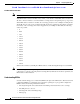
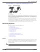
Creating the Spanning Tree Topology
In Figure 8-2, Switch A is elected as the root bridge because the bridge priority of all the switches is set
to the default (32768) and Switch A has the lowest MAC address. However, due to traffic patterns,
number of forwarding ports, or link types, Switch A might not be the ideal root bridge. By increasing
the priority (lowering the numerical value) of the ideal switch so that it becomes the root bridge, you
force an STP recalculation to form a new spanning tree topology with the ideal switch as the root.