
Cisco Nexus 5000 Series Switch CLI Software Configuration Guide, NX-OS 4.0(1a)N1 (OL-16597-01, January 2009)

Send feedback to nx5000-docfeedback@cisco.com
8-6
Cisco Nexus 5000 Series Switch CLI Software Configuration Guide
OL-16597-01
Chapter 8 Configuring Rapid PVST+
Information About Rapid PVST+
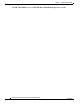
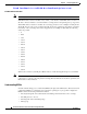
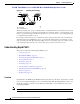
Figure 8-2 Spanning Tree Topology
When the spanning tree topology is calculated based on default parameters, the path between source and
destination end stations in a switched network might not be ideal. For instance, connecting higher-speed
links to a port that has a higher number than the current root port can cause a root-port change. The goal
is to make the fastest link the root port.
For example, assume that one port on Switch B is a fiber-optic link, and another port on Switch B (an
unshielded twisted-pair [UTP] link) is the root port. Network traffic might be more efficient over the
high-speed fiber-optic link. By changing the STP port priority on the fiber-optic port to a higher priority
(lower numerical value) than the root port, the fiber-optic port becomes the new root port.
Understanding Rapid PVST+
This section includes the following Rapid PVST+ topics:
• Overview, page 8-6
• Rapid PVST+ BPDUs, page 8-8
• Proposal and Agreement Handshake, page 8-8
• Protocol Timers, page 8-9
• Port Roles, page 8-10
• Port States, page 8-11
• Synchronization of Port Roles, page 8-13
• Detecting Unidirectional Link Failure, page 8-14
• Port Cost, page 8-15
• Port Priority, page 8-16
Overview
Rapid PVST+ is the IEEE 802.1w (RSTP) standard implemented per VLAN. A single instance of STP
runs on each configured VLAN (if you do not manually disable STP). Each Rapid PVST+ instance on a
VLAN has a single root switch. You can enable and disable STP on a per-VLAN basis when you are
running Rapid PVST+.
Note Rapid PVST+ is the default STP mode for the switch.
187026
DP
DP
RP DP
DP
RP
DP
RP = Root Port
DP = Designated Port
DP
RP
DP
DA
CB