
Cisco Nexus 5000 Series Switch CLI Software Configuration Guide, NX-OS 4.0(1a)N1 (OL-16597-01, January 2009)

Send feedback to nx5000-docfeedback@cisco.com
37-2
Cisco Nexus 5000 Series Switch CLI Software Configuration Guide
OL-16597-01
Chapter 37 Configuring and Managing VSANs
Information About VSANs
• Fabric-related configurations in one VSAN do not affect the associated traffic in another VSAN.
• Events causing traffic disruptions in one VSAN are contained within that VSAN and are not
propagated to other VSANs.
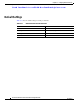
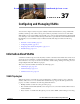
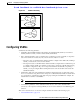
Figure 37-1 shows a fabric with three switches, one on each floor. The geographic location of the
switches and the attached devices is independent of their segmentation into logical VSANs. No
communication between VSANs is possible. Within each VSAN, all members can talk to one another.
Figure 37-1 Logical VSAN Segmentation
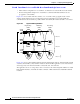
Figure 37-2 shows a physical Fibre Channel switching infrastructure with two defined VSANs: VSAN
2 (dashed) and VSAN 7 (solid). VSAN 2 includes hosts H1 and H2, application servers AS2 and AS3,
and storage arrays SA1 and SA4. VSAN 7 connects H3, AS1, SA2, and SA3.
The application servers or storage arrays can be connected to the switch using Fibre Channel or virtual
Fibre Channel interfaces. A VSAN can include a mixture of Fibre Channel and virtual Fibre Channel
interfaces.
Switch 1
Switch 2
Switch 3
Engineering
VSAN
Marketing
VSAN
Accounting
VSAN
Floor 3
Floor 2
Floor 1
79532