
Cisco Nexus 5000 Series Switch CLI Software Configuration Guide, NX-OS 4.0(1a)N1 (OL-16597-01, January 2009)

Send feedback to nx5000-docfeedback@cisco.com
3-16
Cisco Nexus 5000 Series Switch CLI Software Configuration Guide
OL-16597-01
Chapter 3 Configuring the Switch
NTP Configuration
Time synchronization happens when several frames are exchanged between clients and servers. The
switches in client mode know the address of one or more NTP servers. The servers act as the time source
and receive client synchronization requests.
By configuring an IP address as a peer, the switch will obtain and provide time as required. The peer is
capable of providing time on its own and is capable of having a server configured. If both these instances
point to different time servers, your NTP service is more reliable. Even if the active server link is lost,
you can still maintain the right time due to the presence of the peer.
Tip If an active server fails, a configured peer helps in providing the NTP time. Provide a direct NTP server
association and configure a peer to ensure backup support if the active server fails.
If you only configure a peer, the most accurate peer takes on the role of the NTP server and the other
peer(s) acts as a peer(s).
NTP Configuration Guidelines
The following guidelines apply to all NTP configurations:
• You should have a peer association with another switch only when you are sure that your clock is
reliable (which means that you are a client of a reliable NTP server).
• A peer configured alone takes on the role of a server and should be used as backup. If you have two
servers, then you can have several switches point to one server, and the remaining switches to the
other server. You would configure peer association between these two sets, which forces the clock
to be more reliable.
• If you only have one server, it is better for all the switches to have a client association with that
server.
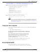
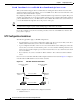
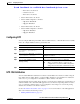
Not even a server down time will affect well-configured switches in the network. Figure 3-2 displays a
network with two NTP stratum 2 servers and two switches.
Figure 3-2 NTP Peer and Server Association
In this configuration, the switches were configured as follows:
• Stratum 2 Server 1
85532
From lower stratum
server-1
From lower stratum
server-2
Peer association
Peer association
Server
association
Server
association
Stratum-2
Server-2
Stratum-2
Server-1
Switch-1 Switch-2