
Instruction Manual

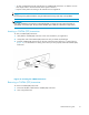


3. Slide the CWDM (SFP) transceiver out of the device module slot.
NOTE:
IfyourCWDM(SFP)transceiverdoesnotslideeasilyfromthemoduleslot,useagentle
side-to-side rocking motion while firmly pulling the CWD M (SFP) transceiver out.
4. PutthedustcoverssecurelyontheCWDM(SFP)transceivers.
Cabling HP CWDM MUX modules
Connecting fi ber optic cables from the HP CWDM MUX module ports to the CWDM (SFP) transceivers is
simplified by color coding. See Table 2 for the color-coded labels and their corresponding wavelength
connectors.
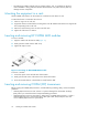
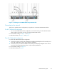
Figure 13 shows how to connect cab les from the C WDM (SFP) transceiver to the equipment por ts on
a HP CWDM MUX module.
To connect fiber optic cables from the CWDM (SFP) transceiver to the HP CWDM MUX module:
1. Clean all fiber optic connectors on the c able before i nser ting them into the HP CW DM MUX m od ule.
2. Connect one end of the fiber optic cable to the HP CWDM M UX module connector and connect
the other end of the fiber optic cable to the corresponding CWDM (SFP) transceiver installed on
the FC or network device.
NOTE:
Consult your network planning diagram to map the fiber optic cables to the CWDM (SFP )
transceivers and e quipment ports on the HP CWDM MUX modules.
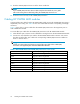
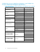
Table 2 HP CWDM MUX and CW DM (SFP) transceiver col or codes
Label color Connector (Wavelength) Description
Gray
Longwave 1470 nm single-mode.
Violet Longwave 1
490 nm single-mode.
Blue Longwave 1510 nm single-mode.
Green
Longwave 1530 nm single-mode.
Yellow Longwave 1550 nm single-mode.
Orange
Longwave 1570 nm single-mode.
Red Longwave 1590 nm single-mode.
Brown
Longwav
e1610nmsingle-mode.
22
Installing HP CWDM MUX mod ules