Compaq 7+ 1300 Tablet and Compaq 7 1200 Tablet Maintenance and Service Guide IMPORTANT! This document is intended for HP authorized service providers only.
© Copyright 2013 Hewlett-Packard Development Company, L.P. Bluetooth is a trademark owned by its proprietor and used by Hewlett-Packard Company under license. SD Logo is a trademark of its proprietor. The information contained herein is subject to change without notice. The only warranties for HP products and services are set forth in the express warranty statements accompanying such products and services. Nothing herein should be construed as constituting an additional warranty.
Safety warning notice WARNING! To reduce the possibility of heat-related injuries or of overheating the device, do not place the device directly on your lap or obstruct the device air vents. Use the device only on a hard, flat surface. Do not allow another hard surface, such as an adjoining optional printer, or a soft surface, such as pillows or rugs or clothing, to block airflow. Also, do not allow the AC adapter to contact the skin or a soft surface, such as pillows or rugs or clothing, during operation.
iv Safety warning notice
Table of contents 1 Product description ........................................................................................................... 1 2 External component identification ..................................................................................... 3 3 Illustrated parts catalog .................................................................................................... 5 Locating the serial number, product number, and model number .............................................
Specifications ................................................................................................................. 25 7 Statement of Volatility .................................................................................................... 26 Non-volatile memory usage ..................................................................................................... 28 Questions and answers ...............................................................................................
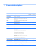
1 Product description Category Description Product Name Compaq 7+ 1300 Tablet Compaq 7+ 1300 Tablet Compaq 7 1200 Tablet x Compaq 7 1200 Tablet x Processor AllWinner® A31S 1.00-GHz quad core soldered on-chip (SOC) processor x Panel 7.0-in, (1024×600), IPS TouchScreen display panel with 5-point, capacitive touch x 7.
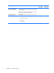
Category Description Power requirements Supports a 2800-mAh, Li-ion battery (non-removable), USB charging battery Compaq 7+ 1300 Tablet Compaq 7 1200 Tablet x x Supports an HP 5V-2A, USB, AC adapter with duck head DC plug and localized cable plug support 2 Operating system Preinstalled: Android 4.2.2 (Android 4.
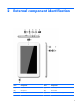
2 External component identification Item Component Item Component (1) Micro SD Card Reader slot (6) Front-facing webcamera (2) Microphone (7) Power button (3) Micro USB port (8) Volume control buttons (2) 3
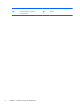
4 Item Component Item Component (4) Audio-out (headphone)/Audio-in (microphone) jack (9) Speaker (5) Rear-facing webcamera Chapter 2 External component identification
3 Illustrated parts catalog Locating the serial number, product number, and model number The product name (1), product model (2), product number (3), and serial number (4) of your tablet are located on the bottom edge of the tablet. You may need this information when you travel internationally or when you contact support.
Tablet major components 6 Item Component (1) Back cover Spare part number For use only on Compaq 7+ 1300 Tablet models 756827-001 For use only on Compaq 7 1200 Tablet models 754935-001 (2) Battery, 3.7-V, 2800-mAh, Li-ion (includes cables) 754936-001 (3) Antenna Kit (includes wireless antenna transceiver and cable) 754934-001 (4) Microphone (includes cable) 754529-001 (5) 0.
Item Component Spare part number 7-in., LCD, TouchScreen IPS display panel assembly for use only on Compaq 7+ 1300 Tablet models 755969-001 7-in., LCD, TouchScreen TN display panel assembly for use only on Compaq 7 1200 Tablet models 754940-001 Miscellaneous parts Component Spare part number 0.3-W, 240-W, 50/60-Hz, 5.0-V, 2-A AC adapter 752105-001 Compaq 7+ 1300 Tablet equipped with a 7-in., LCD, TouchScreen IPS display, an AllWinner A31S 1.00-GHz quad core processor, 1.
8 Spare part number Description 754942-001 System board equipped with an AllWinner A31S 1.00-GHz quad core processor, 1.0-GB LP-DDR2 system memory, and an 8.0-GB Nand flash drive 755197-001 Speaker Kit (includes speaker and cables) 755969-001 7-in., LCD, TouchScreen IPS display panel assembly for use only on Compaq 7+ 1300 Tablet models 755970-001 Compaq 7+ 1300 Tablet equipped with a 7-in., LCD, TouchScreen IPS display, an AllWinner A31S 1.00-GHz quad core processor, 1.
4 Removal and replacement preliminary requirements Tools required You will need the following tools to complete the removal and replacement procedures: ● Magnetic screw driver ● Phillips P0 screw driver ● Plastic case utility tool ● Torx T5 screw driver Service considerations The following sections include some of the considerations that you must keep in mind during disassembly and assembly procedures.
Grounding guidelines Electrostatic discharge damage Electronic components are sensitive to electrostatic discharge (ESD). Circuitry design and structure determine the degree of sensitivity. Networks built into many integrated circuits provide some protection, but in many cases, ESD contains enough power to alter device parameters or melt silicon junctions. A discharge of static electricity from a finger or other conductor can destroy static-sensitive devices or microcircuitry.
Packaging and transporting guidelines Follow these grounding guidelines when packaging and transporting equipment: ● To avoid hand contact, transport products in static-safe tubes, bags, or boxes. ● Protect ESD-sensitive parts and assemblies with conductive or approved containers or packaging. ● Keep ESD-sensitive parts in their containers until the parts arrive at static-free workstations. ● Place items on a grounded surface before removing items from their containers.
Equipment guidelines Grounding equipment must include either a wrist strap or a foot strap at a grounded workstation. ● When seated, wear a wrist strap connected to a grounded system. Wrist straps are flexible straps with a minimum of one megohm ±10% resistance in the ground cords. To provide proper ground, wear a strap snugly against the skin at all times. On grounded mats with banana-plug connectors, use alligator clips to connect a wrist strap.
5 Removal and replacement procedures Tablet component replacement procedures CAUTION: Tablet components described in this chapter should only be accessed by an authorized service provider. Accessing these parts can damage the tablet and void the warranty. This chapter provides removal and replacement procedures for authorized service provider only parts. There are as many as 6 screws that must be removed, replaced, and/or loosened when servicing the tablet.
CAUTION: Before positioning the tablet with the display panel facing down, make sure the work surface is clear of tools, screws, and any other foreign objects. Failure to follow this caution can result in damage to the display panel assembly. 14 1. Place the tablet on a flat surface, display panel side down, with the power button and volume buttons toward you. 2. Remove the four Torx5 T5M1.4×4.0 screws that secure the back cover to the display panel assembly. 3.
6. Remove the display panel assembly (3) from the back cover. Reverse this procedure to install the back cover. Battery Description Spare part number Battery, 3.7-V, 2800-mAh, Li-ion (includes cables) 754936-001 Before removing the battery, follow these steps: 1. Turn off the tablet. If you are unsure whether the tablet is off or in Hibernation, turn the tablet on, and then shut it down through the operating system. 2.
CAUTION: Before positioning the tablet with the display panel facing down, make sure the work surface is clear of tools, screws, and any other foreign objects. Failure to follow this caution can result in damage to the display panel assembly. 1. Place the display panel assembly on a flat surface, display panel side down, with the power button and volume buttons toward you. 2. Unsolder the battery cables from the terminals (1) on the system board.
Remove the antenna board: 1. Unsolder the antenna cable from the system board wireless terminal (1). 2. Release the antenna cable from the routing channel (2) between the battery and the system board. 3. Detach the antenna transceiver (3) from the display panel assembly. (The antenna transceiver is attached to the display panel assembly with double-sided adhesive.) 4. Remove the antenna transceiver and cable. Reverse this procedure to install the antenna.
Remove the speaker: 1. Unsolder the speaker cables (1) from the system board terminals. NOTE: When installing the speaker, the speaker red cable should be soldered to the system board “+” terminal, and the speaker black cable should be soldered to the “-” terminal. 2. Release the speaker cable (2) from the retention clip built into the display panel assembly. 3. Detach the speaker (3) from the display panel assembly. (The speaker is attached to the display panel assembly with double-sided adhesive.
4. Remove the back cover (see Back cover on page 13). 5. Disconnect the battery cables from the system board (see Battery on page 15). Remove the rear-facing webcamera: 1. Turn the system board upside down. 2. Release the zero insertion force (ZIF) connector (1) to which the rear-facing webcamera is attached, and then disconnect the rear-facing webcamera from the system board. 3. Remove the rear-facing webcamera (2) and cable. Reverse this procedure to install the rear-facing webcamera.
Remove the microphone: 1. Unsolder the microphone cables (1) from the system board terminals. NOTE: When installing the microphone, the microphone red cable should be soldered to the system board “+” terminal, and the microphone black cable should be soldered to the “-” terminal. 2. Release the microphone (2) from the retention molding built into the display panel assembly. 3. Remove the microphone and cable. Reverse this procedure to install the microphone.
Remove the front-facing webcamera: 1. Release the ZIF connector (1) to which the front-facing webcamera cable is attached, and then disconnect the front-facing webcamera cable from the system board. 2. Release the front-facing webcamera (2) from the retention molding built into the display panel assembly. 3. Remove the front-facing webcamera and cable. Reverse this procedure to install the front-facing webcamera.
2. Detach the power/volume button board (2) from the display panel assembly. (The power/volume button board is attached to the display panel assembly with double-sided adhesive. 3. Remove the power/volume button board and cable. Reverse this procedure to install the power/volume button board. System board Description Spare part number System board equipped with an AllWinner A31S 1.00-GHz quad core processor, 1.0-GB LPDDR2 system memory, and an 8.
Remove the system board: 1.
Reverse this procedure to install the system board.
6 Specifications Metric U.S. Width 12.2 cm 4.8 in Depth 0.8 cm 0.3 in Height 19.3 cm 7.6 in Weight (lowest weight configuration) 0.32 g 0.70 lb Dimensions Input power The tablet operates on DC power, which can be supplied by an AC or a DC power source. The AC power source must be rated at 100—240 V, 50/60 Hz. NOTE: The tablet can operate on DC power using an industry-standard micro-A or micro-B USB cable. The HP 5V 2A adapter included with your tablet is recommended for charging the tablet.
7 Statement of Volatility The purpose of this document is to provide general information regarding non-volatile memory in industry-standards based HP Business Notebook PC systems and provide general instructions for restoring nonvolatile memory that can contain personal data after the system has been powered off and the hard drive has been removed. HP Business Notebook PC products that use Intel-based or AMD®-based system boards contain volatile DDR memory.
f. If an Automatic DriveLock password is set, select the Security menu, scroll down to Automatic DriveLock, then select the desired hard drive and disable protection. Repeat this procedure if more than one hard drive has an Automatic DriveLock password. g. Select the File menu, then Reset BIOS Security to factory default. Click yes at the warning message. h. Select the File menu, then Save Changes and Exit. i. Reboot the system.
Non-volatile memory usage 28 Non Volatile Memory Type Amount (Size) Does this memory store customer data? Does this memory retain data when power is removed? What is the purpose of this memory? How is data input into this memory? How is this memory write protected? Real Time Clock (RTC) battery backed-up CMOS configuration memory (CMOS) 256 Bytes No Yes Stores system date and time and limited keyboard controller data. Using the F10 Setup utility or changing the Microsoft Windows date and time.
Non Volatile Memory Type Amount (Size) Does this memory store customer data? Does this memory retain data when power is removed? What is the purpose of this memory? How is data input into this memory? How is this memory write protected? System BIOS 4 to 5 MBytes Yes Yes Store system BIOS code and PC configuration data. System BIOS code is programmed at the factory. Code is updated when the system BIOS is updated.
30 Non Volatile Memory Type Amount (Size) Does this memory store customer data? Does this memory retain data when power is removed? What is the purpose of this memory? How is data input into this memory? How is this memory write protected? Bluetooth flash 2 MBits No Yes Stores Bluetooth configuration and firmware. Programmed at the factory. Tools for writing data to this memory are not publicly available but can be obtained from the silicon vendor.
Questions and answers 1. 2. How can the BIOS settings be restored (returned to default settings)? a. Turn on or restart the computer and press F10 when prompted near the bottom of the display. b. Select File, then select Restore defaults. c. Follow the on-screen instructions. d. Select File, save changes and exit, then press Enter.
8 Power cord set requirements The wide-range input feature of the tablet permits it to operate from any line voltage from 100 to 120 volts AC, or from 220 to 240 volts AC. The 3-conductor power cord set included with the tablet meets the requirements for use in the country or region where the equipment is purchased. Power cord sets for use in other countries and regions must meet the requirements of the country or region where the tablet is used.
Country/region Accredited agency Applicable note number Germany VDE 1 Italy IMQ 1 Japan METI 3 The Netherlands KEMA 1 Norway NEMKO 1 The People's Republic of China COC 5 South Korea EK 4 Sweden CEMKO 1 Switzerland SEV 1 Taiwan BSMI 4 The United Kingdom BSI 1 The United States UL 2 1. The flexible cord must be Type HO5VV-F, 3-conductor, 1.0-mm² conductor size.
9 Recycling When a non-rechargeable or rechargeable battery has reached the end of its useful life, do not dispose of the battery in general household waste. Follow the local laws and regulations in your area for battery disposal. HP encourages customers to recycle used electronic hardware, HP original print cartridges, and rechargeable batteries. For more information about recycling programs, see the HP Web site at http://www.hp.com/recycle.
Index A AC adapter, spare part number 7 antenna removal 16 spare part number 6, 7, 16 Antenna Kit, spare part number 6, 7, 16 audio, product description 1 audio-in jack 4 audio-out jack 4 B back cover removal 13 spare part numbers 6, 7, 8, 13 battery removal 15 spare part number 6, 7, 15 buttons power 3 volume control 3 C cables, service considerations 9 card reader slot 3 connectors, service considerations 9 D display panel assembly, spare part numbers 6, 7, 8, 13 display panel, product description 1 E el
R rear-facing webcamera location 4 removal 18 spare part number 6, 7, 18 S Screw Kit, spare part number 7 sensor, product description 1 service considerations cables 9 connectors 9 plastic parts 9 serviceability, product description 2 speaker location 4 removal 17 spare part number 6, 8, 17 Speaker Kit, spare part number 6, 8, 17 system board removal 22 spare part number 6, 8, 22 T tablet major components 6 spare part numbers 7, 8 specifications 25 tools required 9 transporting guidelines 11 U USB extension