Hardware Reference Guide HP Compaq Business PC dc7600 Ultra-Slim Desktop Model Document Part Number: 383421-001 May 2005 This guide provides detailed information on the features and use of the HP Compaq dc7600 Ultra-Slim Desktop, and includes instructions for removing and replacing internal components.
© Copyright 2005 Hewlett-Packard Development Company, L.P. The information contained herein is subject to change without notice. Microsoft and Windows are trademarks of Microsoft Corporation in the U.S. and other countries. The only warranties for HP products and services are set forth in the express warranty statements accompanying such products and services. Nothing herein should be construed as constituting an additional warranty.
Contents 1 Product Features Standard Configuration Features. . . . . . . . . . . . . . . . . . . . . . . . . . . . . . . . . . . . . . . . . . Front Panel Components . . . . . . . . . . . . . . . . . . . . . . . . . . . . . . . . . . . . . . . . . . . . . . . . Rear Panel Components . . . . . . . . . . . . . . . . . . . . . . . . . . . . . . . . . . . . . . . . . . . . . . . . Standard Keyboard Components. . . . . . . . . . . . . . . . . . . . . . . . . . . . . . . . . . . . . . . . . . Windows Logo Key. .
Contents A Specifications B Battery Replacement C Security Provisions Installing an Optional Security Lock. . . . . . . . . . . . . . . . . . . . . . . . . . . . . . . . . . . . . . . Cable Lock . . . . . . . . . . . . . . . . . . . . . . . . . . . . . . . . . . . . . . . . . . . . . . . . . . . . . . . Padlock . . . . . . . . . . . . . . . . . . . . . . . . . . . . . . . . . . . . . . . . . . . . . . . . . . . . . . . . . . Universal Chassis Clamp Lock. . . . . . . . . . . . . . . . . . . . . . . . . . .
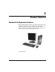
1 Product Features Standard Configuration Features The Ultra-Slim Desktop computer comes with features that may vary depending on the model. For a complete listing of the hardware and software installed in the computer, run the diagnostics utility. Instructions for using this utility is provided in the Troubleshooting Guide on the Documentation and Diagnostics CD. Ultra-Slim Desktop Hardware Reference Guide www.hp.
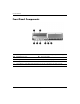
Product Features Front Panel Components 1 MultiBay 5 Universal Serial Bus (USB) Connector (2) 2 MultiBay Eject Lever 6 Power On Light 3 Microphone Connector 7 Hard Drive Activity Light 4 Headphone Connector 8 Dual-State Power Button ✎ Any USB device (including keyboard and mouse) can be connected to any USB connector. 1–2 www.hp.
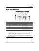
Product Features Rear Panel Components 1 Power Cord Connector 7 n RJ-45 Network Connector 2 Voltage Select Switch 8 l Parallel Connector 9 c Monitor Connector - Y q j Line-In Audio Connector (blue) w c Digital Video Interface (DVI–D) Monitor Connector (optional) 3 4 b PS/2 Mouse Connector (green) a PS/2 Keyboard Connector (purple) 5 o Universal Serial Bus (USB) 6 m Serial Connector Line-Out Connector (green) (for powered devices) ✎ Arrangement and number of connectors may vary by m
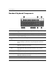
Product Features Standard Keyboard Components 1 Function Keys Perform special functions, depending on the software application being used. 2 Editing Keys Include the following: Insert, Home, Page Up, Delete, End, and Page Down. 3 Status Lights Indicate the status of the computer and keyboard settings (Num Lock, Caps Lock, and Scroll Lock). 4 Numeric Keys Work like a calculator keypad. 5 Arrow Keys Used to navigate through a document or Web site.
Product Features Windows Logo Key Use the Windows Logo Key in combination with other keys to perform certain functions available in the Windows operating system. Windows Logo Key Display or hide the Start menu. Windows Logo Key + Break Display the System Properties dialog box. Windows Logo Key + F1 Display Help for the Windows operating system. Windows Logo Key + Tab Switch between open items. Windows Logo Key + e Open My Computer. Windows Logo Key + f Search for a file or folder.
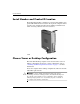
Product Features Serial Number and Product ID Location Each Ultra-Slim Desktop computer has a unique serial number and a product ID number that are located on the top of the computer when it is in the tower configuration. Keep these numbers available for use when contacting customer service for assistance. Serial Number Location Choose Tower or Desktop Configuration The Ultra-Slim Desktop computer can be used in either a tower or desktop configuration.
2 Hardware Upgrades Removing and Replacing the Access Panel Å WARNING: To reduce the risk of personal injury from electrical shock and/or hot surfaces, be sure to disconnect the power cord from the wall outlet, and allow the internal system components to cool before touching. Å WARNING: To reduce the risk of electrical shock, fire, or damage to the equipment, do not plug telecommunications or telephone connectors into the network interface controller (NIC) receptacles.
Hardware Upgrades optional cable lock may be used to secure the access panel, ✎ An preventing access to internal components including system memory, the internal hard drive, and the MultiBay security catch. It may also be used to secure the computer to a fixed object. For more information on installing or removing these security devices, refer to Appendix C, “Security Provisions.” 4. Remove the optional cable lock, if installed. 5. Position the computer on its side with the rubber pads on the bottom.
Hardware Upgrades To replace the access panel: 1. Ensure that the panel is aligned properly, then slide it toward the front of the computer and tighten the thumbscrew to secure it. 2. Install the optional cable lock, if desired. 3. Replace the stand, if desired. 4. Reconnect all external devices, plug the power cord into the power outlet, and turn the computer on. 5. Use Computer Setup to enable the Smart Cover Sensor, if desired.
Hardware Upgrades 7. Remove the MultiBay daughter card by pulling it straight up out of the computer. Removing the MultiBay Daughter Card 2–4 www.hp.
Hardware Upgrades 8. Disconnect the fan cable. Disconnecting the Fan Cable 9. Disconnect the speaker cable. Disconnecting the Speaker Cable Hardware Reference Guide www.hp.
Hardware Upgrades 10. Pull the lever on each side of the computer chassis up and toward the rear of the computer 1, and pull the front bezel and attached MultiBay forward and off the computer 2. Removing the Front Bezel and MultiBay To replace the front bezel and MultiBay: 1. Ensure that the front bezel and MultiBay are aligned properly, then slide the assembly toward the rear of the computer until it is properly seated. The latch on each side of the computer chassis will return to its original position.
Hardware Upgrades Attaching and Removing the Tower Stand To use the Ultra-Slim Desktop computer in the tower configuration: 1. Exit all software applications, shut down the operating system software, turn off the computer and any external devices, then disconnect the power cord from the power outlet. 2. Rotate the computer into the tower position with the MultiBay and fan on the bottom and the PCI expansion slot on the top. Rotating the Computer into the Tower Position Hardware Reference Guide www.hp.
Hardware Upgrades 3. Lower the computer into the stand so that the hooks on the front of the tower stand fit into the vents on the bottom of the computer, then slide the computer back until the hooks engage 1. 4. Tighten the screw to secure the computer to the stand 2. This adds stability and helps to ensure proper airflow to the internal components. Attaching the Stand to the Computer 5. Reconnect all external devices, plug the power cord into the power outlet, and turn the computer on. 2–8 www.hp.
Hardware Upgrades To remove the stand from the computer: 1. Exit all software applications, shut down the operating system software, turn off the computer and any external devices, then disconnect the power cord from the power outlet. 2. Loosen the thumbscrew that secures the computer to the stand 1. 3. Slide the computer forward until it is disengaged from the hooks on the front of the tower stand, then lift the computer up off the stand 2.
Hardware Upgrades 4. Lay the computer on its side with the rubber pads on the bottom. Rotating the Computer into the Desktop Position 5. Reconnect all external devices, plug the power cord into the power outlet, and turn the computer on. 2–10 www.hp.
Hardware Upgrades Installing Additional Memory The computer comes with double data rate 2 synchronous dynamic random access memory (DDR2-SDRAM) dual inline memory modules (DIMMs). DIMMs The memory sockets on the system board can be populated with up to three industry-standard DIMMs. These memory sockets are populated with at least one preinstalled DIMM. To achieve the maximum memory support, you can populate the system board with up to 4GB of memory configured in a high-performing dual channel mode.
Hardware Upgrades DIMM Sockets The system will automatically operate in single channel mode, dual channel Asymmetric mode, or a higher-performing dual channel Interleaved mode, depending on how the DIMMs are installed. ■ The system will operate in a single channel mode if the DIMM sockets are populated in one channel only. ■ The system will operate in dual channel Asymmetric mode if the total memory capacity of the DIMMs in Channel A is not equal to the total memory capacity of DIMMs in Channel B.
Hardware Upgrades DIMM Socket Locations Hardware Reference Guide Item Description Socket Color 1 DIMM socket XMM3, Channel B Black 2 DIMM socket XMM4, Channel B White 3 DIMM socket XMM1, Channel A Black www.hp.
Hardware Upgrades Adding or Removing a Memory Module Ä CAUTION: The memory module sockets have gold-plated metal contacts. When upgrading the memory, it is important to use memory modules with gold-plated metal contacts to prevent corrosion and/or oxidation resulting from having incompatible metals in contact with each other. Ä CAUTION: Static electricity can damage the electronic components of the computer.
Hardware Upgrades 7. To remove a module, a. Press out on both latches 1 of the DIMM socket at the same time. This releases the module and partially pushes it out of the socket. b. Lift the module from the socket 2. Removing Memory Modules Hardware Reference Guide www.hp.
Hardware Upgrades one memory module is used in the system, it must be installed ✎ Ifin only the same socket that held the preinstalled memory module. 8. To install a memory module: a. Press out on both latches 1 of the DIMM socket. b. Match the notch on the module with the tab on the memory socket. Firmly push the module straight into the socket 2, ensuring that the module is fully inserted and properly seated.
Hardware Upgrades 9. Replace the access panel. 10. Replace the stand, if desired. 11. Reconnect all external devices, plug the power cord into the power outlet, and turn the computer on. The computer automatically recognizes the additional memory when you turn on the computer. 12. Use Computer Setup to enable the Smart Cover Sensor, if desired.
Hardware Upgrades Installing an Expansion Card procedure requires an optional expansion card assembly with ✎ This riser card, which can be obtained from HP or an authorized provider. 1. If the Smart Cover Sensor is enabled, restart the computer and enter Computer Setup to disable it. 2. Turn off the computer properly through the operating system, then turn off any external devices. 3. Disconnect the power cord from the power outlet and the computer, and disconnect any external devices. 4.
Hardware Upgrades 7. Remove the expansion slot cover from the new expansion card assembly with riser card: a. If the latch is not open, squeeze the sides of the latch together to release it 1. b. Open the latch 2. c. Pull the expansion card slot cover straight up out of the expansion card assembly 3. Removing an Expansion Card Slot Cover Hardware Reference Guide www.hp.
Hardware Upgrades 8. Install the expansion card: a. If the latch is not open, squeeze the sides of the latch together to release it 1. b. Open the latch 2. c. Slide the expansion card firmly into the expansion card slot until it is properly seated 3. Installing an Expansion Card you install an expansion card, make sure you press firmly on ✎ When the card so that the whole connector seats properly in the expansion card socket. 9.
Hardware Upgrades 10. Line up the tabs on the expansion card assembly with the slots on the computer chassis and press the assembly firmly down into place. Installing the Expansion Card Assembly 11. Connect external cables to the installed card, if needed. Connect internal cables to the system board, if needed. If the card requires audio, connect the audio cable to the connector on the system board labeled “Aux” (located under the power supply cage). 12. Replace the access panel. 13.
Hardware Upgrades Removing an Expansion Card 1. If the Smart Cover Sensor is enabled, restart the computer and enter Computer Setup to disable it. 2. Turn off the computer properly through the operating system, then turn off any external devices. 3. Disconnect the power cord from the power outlet and the computer, and disconnect any external devices. 4. Position the computer on its side with the rubber pads on the bottom.
Hardware Upgrades 7. Remove the expansion card: a. If the latch is not open, squeeze the sides of the latch together to release it 1. b. Open the latch 2. c. Hold the card at each end, and carefully rock it back and forth until the connectors pull free from the socket. d. Pull the expansion card straight up from the socket 3. Be sure not to scrape the card against the expansion card assembly. Removing an Expansion Card 8. Store the card in anti-static packaging. 9.
Hardware Upgrades 10. Replace the access panel. 11. Install the optional cable lock, if desired. 12. Replace the stand, if desired. 13. Reconnect all external devices, plug the power cord into the power outlet, and turn the computer on. 14. Use Computer Setup to enable the Smart Cover Sensor, if desired. Upgrading the Hard Drive Ultra-Slim Desktop supports only Serial ATA (SATA) internal ✎ The hard drives; parallel ATA (PATA) internal hard drives are not supported.
Hardware Upgrades 7. Pull the hard drive latch toward the front of the computer 1. 8. Rotate the right side of the hard drive up until it stops 2, then pull the drive out to the right 3. Removing the Internal Hard Drive Hardware Reference Guide www.hp.
Hardware Upgrades removing cables, pull on the connector instead of the cable ✎ When itself. This will help prevent cable damage. 9. Disconnect the data cable 1 from the hard drive by pulling the connector out of the socket in the hard drive. 10. Disconnect the other end of the data cable from the system board. 11. Disconnect the power cable 2 from the hard drive by pulling the connector out of the socket in the hard drive. Disconnecting the Data Cable and Power Cable from the Hard Drive 12.
Hardware Upgrades 13. Connect the data cable to the data connector on the system board. 14. Connect the data cable 1 and power cable 2 to the new hard drive. Data 1 and Power 2 Cable Connector Locations 15. Gently place the left side of the hard drive in place, then rotate the right side of the drive down until it locks. 16. Replace the front bezel and MultiBay assembly. 17. Replace the access panel. 18. Replace the stand, if desired. 19.
Hardware Upgrades replacing the hard drive, insert the Restore Plus! CD ✎ toAfterrestore the operating system, software drivers, and any software applications that were preinstalled on the computer. Follow the instructions in the guide included with the Restore Plus! CD. When the restore process has completed, install any personal files that you backed up before replacing the hard drive. Working with the MultiBay The MultiBay is a special drive bay that supports a variety of optional 12.
Hardware Upgrades “Hot-Plugging” or “Hot-Swapping” MultiBay Drives Ä CAUTION: To prevent damage to the computer, the drive, and any data stored on the drive: If you are inserting or removing a hard drive, shut down the computer. Never remove a hard drive while the computer is on or on standby. To ensure that the computer is not on standby, turn the computer on, then shut it down.
Hardware Upgrades 6. Rotate the catch toward the left side of the computer until it is engaged. Engaging the MultiBay Security Catch 7. Replace the access panel. 8. Replace the stand, if desired. 9. Reconnect all external devices, plug the power cord into the power outlet, and turn the computer on. 10. Use Computer Setup to enable the Smart Cover Sensor, if desired. To release the MultiBay security catch: 1.
Hardware Upgrades 4. Position the computer on its side with the rubber pads on the bottom. (If the computer is being used in the tower configuration, remove the computer from the stand. Refer to “Attaching and Removing the Tower Stand” on page 2–7 for more information.) 5. Remove the access panel. Refer to “Removing and Replacing the Access Panel” on page 2–1 for more information. 6. Rotate the catch toward the right side of the computer until it is disengaged. Releasing the MultiBay Security Catch 7.
Hardware Upgrades Removing a Drive from the MultiBay 1. Remove any removable media, such as a compact disc, from the drive. 2. Before removing an optical or diskette drive, stop the drive using the Safely Remove Hardware icon on the Windows task bar. 3. If you are not hot-swapping a CD-ROM or diskette drive, exit all software applications, shut down the operating system software, and turn off the computer. 4. Release the MultiBay security catch, if it has been engaged.
Hardware Upgrades Inserting a Drive into the MultiBay 1. Remove any removable media, such as a compact disc, from the drive. 2. If you are not hot-swapping a CD-ROM or diskette drive, exit all software applications, shut down the operating system software, and turn off the computer. 3.
Hardware Upgrades If the device does not start, ensure that the necessary device drivers are installed on the system. If they are not available, they may be downloaded, at no cost, from the HP Web site at www.hp.com. Click support & drivers, select Download drivers and software, enter the model number of the computer, and press Enter. Partitioning and Formatting a MultiBay Hard Drive must be logged on as an administrator or a member of the ✎ You Administrators group in order to complete this procedure. 1.
A Specifications Ultra-Slim Desktop Desktop Dimensions (in the tower position) Height Width Depth Approximate Weight Weight Supported (maximum distributed load in desktop position) 12.40 in 2.75 in 13.18 in 315 mm 70 mm 335 mm 13.9 lb 6.3 kg 77 lb 35 kg 50° to 95° F -22° to 140° F 10° to 35° C -30° to 60° C Temperature Range (values subject to change with increasing altitude above sea level) Operating Nonoperating ✎ Operating temperature is derated 1.
Specifications Ultra-Slim Desktop (Continued) Mechanical Shock (11ms 1/2 sine shock pulse) 5 Gs 20 Gs Operating Nonoperating Vibration (random, Gs nominal) .25 .
B Battery Replacement The battery that comes with the computer provides power to the real-time clock. When replacing the battery, use a battery equivalent to the battery originally installed in the computer. The computer comes with a 3-volt lithium coin cell battery. lifetime of the lithium battery can be extended by plugging the ✎ The computer into a live AC wall socket. The lithium battery is only used when the computer is NOT connected to AC power.
Battery Replacement Ä CAUTION: Static electricity can damage the electronic components of the computer or optional equipment. Before beginning these procedures, ensure that you are discharged of static electricity by briefly touching a grounded metal object. 1. Use Computer Setup to disable the Smart Cover Sensor, if necessary. Refer to the Computer Setup (F10) Utility Guide on the Documentation and Diagnostics CD for more information. 2. Remove the drive from the MultiBay.
Battery Replacement 8. Locate the battery and battery holder on the system board. 9. Release the battery latch and lift the battery out of the holder 1. 10. Holding the replacement battery with the positive side up, push the battery down until the latch snaps over the upper edge of the battery 2. Replacing the Battery the battery has been replaced, use the following steps to ✎ After complete this procedure. 11. Replace the power supply: a. Gently place the left side of the power supply in place. a.
Battery Replacement 14. Engage the MultiBay security catch, if desired. 15. Replace the computer access panel. 16. Reconnect all external devices, plug the power cord into the power outlet, and turn the computer on. 17. Using Computer Setup: a. Reset the date and time. b. Reset your passwords. c. Reset any special system setups. d. Enable the Smart Cover Sensor, if necessary. Refer to the Computer Setup (F10) Utility Guide on the Documentation and Diagnostics CD for more information. B-4 www.hp.
C Security Provisions information on data security features, refer to the Computer Setup ✎ For (F10) Utility Guide and the Desktop Management Guide on the Documentation and Diagnostics CD and the HP ProtectTools Security Manager Guide (some models) at www.hp.com. Installing an Optional Security Lock The security locks displayed below and on the following pages can be used to secure the Ultra-Slim Desktop. Cable Lock Installing a Cable Lock Hardware Reference Guide www.hp.
Security Provisions Padlock Installing a Padlock C–2 www.hp.
Security Provisions Universal Chassis Clamp Lock Without Security Cable 1. Thread the keyboard and mouse cables through the lock. Hardware Reference Guide www.hp.
Security Provisions 2. Screw the lock to the chassis using the screw provided. 3. Insert the plug into the lock 1 and push the button 2 in to engage the lock. Use the key provided to disengage the lock. C–4 www.hp.
Security Provisions With Security Cable 1. Fasten the security cable by looping it around a stationary object. 2. Thread the keyboard and mouse cables through the lock. Hardware Reference Guide www.hp.
Security Provisions 3. Screw the lock to the chassis using the screw provided. 4. Insert the plug end of the security cable into the lock 1 and push the button in to engage the lock 2. Use the key provided to disengage the lock. C–6 www.hp.
D Electrostatic Discharge A discharge of static electricity from a finger or other conductor may damage system boards or other static-sensitive devices. This type of damage may reduce the life expectancy of the device. Preventing Electrostatic Damage To prevent electrostatic damage, observe the following precautions: ■ Avoid hand contact by transporting and storing products in static-safe containers. ■ Keep electrostatic-sensitive parts in their containers until they arrive at static-free workstations.
Electrostatic Discharge ■ Use heelstraps, toestraps, or bootstraps at standing workstations. Wear the straps on both feet when standing on conductive floors or dissipating floor mats. ■ Use conductive field service tools. ■ Use a portable field service kit with a folding static-dissipating work mat. If you do not have any of the suggested equipment for proper grounding, contact an authorized dealer, reseller, or service provider.
E Computer Operating Guidelines, Routine Care and Shipping Preparation Computer Operating Guidelines and Routine Care Follow these guidelines to properly set up and care for the computer and monitor: Hardware Reference Guide ■ Keep the computer away from excessive moisture, direct sunlight, and extremes of heat and cold. For information about the recommended temperature and humidity ranges for the computer, refer to Appendix A, “Specifications” in this guide.
Computer Operating Guidelines, Routine Care and Shipping Preparation ■ Turn off the computer before you do either of the following: ❏ Wipe the exterior of the computer with a soft, damp cloth as needed. Using cleaning products may discolor or damage the finish. ❏ Occasionally clean the air vents on all vented sides of the computer. Lint, dust, and other foreign matter can block the vents and limit the airflow.
Computer Operating Guidelines, Routine Care and Shipping Preparation Shipping Preparation Follow these suggestions when preparing to ship the computer: 1. Back up the hard drive files on PD discs, tape cartridges, CDs, or diskettes. Be sure that the backup media is not exposed to electrical or magnetic impulses while stored or in transit. hard drive locks automatically when the system power is ✎ The turned off. 2. Remove and store any program diskettes from the diskette drives. 3.
Index A expansion card FireWire 2–17 graphics 2–17 installing 2–17 to 2–21 modem 2–17 NIC 2–17 removing 2–22 to 2–24 wireless LAN 2–17 access panel removal of 2–1 to 2–2 audio connector 1–3 B battery replacement B–1 C cable connectors, hard drive 2–27 cable lock, optional C–1 CD drive, MultiBay 2–28 components front panel 1–2 rear panel 1–3 computer operating guidelines E–1 shipping preparation E–3 configuration desktop 1–6 configuration, tower or desktop 1–6 connectors, hard drive 2–27 F FireWire, PCI
Index I installing hard drives, MultiBay 2–33 to 2–34 internal hard drive 2–24 to 2–27 MultiBay drives 2–33 to 2–34 optical drive 2–29 PCI expansion card 2–17 to 2–21 internal hard drive, upgrading 2–24 to 2–27 K keyboard 1–4 PS/2 port 1–3 Windows Logo Key 1–5 L locks cable C–1 padlock C–2 N M NIC, PCI expansion card 2–17 memory, system 2–11 to 2–17 adding or removing modules 2–14 to 2–17 modem, PCI expansion card 2–17 monitor connector 1–3 DVI-D 1–3 mouse PS/2 connector 1–3 MPEG-2 software 2–28 Ind
Index R rear panel components 1–3 removing PCI expansion card 2–22 to 2–24 RJ-45 connector 1–3 S security C–1 MultiBay 2–29 to 2–31 serial connector 1–3 serial number 1–6 shipping preparation E–3 specifications A–1 static electricity D–1 SuperDisk LS-240 drive, MultiBay 2–28 T tower configuration 1–6 U USB 1–3 W Windows Logo Key 1–5 wireless LAN, PCI expansion card 2–17 Hardware Reference Guide www.hp.