Hardware Reference Manual HP Compaq Business Desktop dx2480 Microtower Model March 2008 This guide provides basic information for upgrading this computer model.
Hardware Reference Guide HP Compaq Business Desktop dx2480 Microtower Model March 2008 This guide provides basic information for upgrading this computer model.
© Copyright 2008 Hewlett-Packard Development Company, L.P. The information contained herein is subject to change without notice. Microsoft, MS-DOS, Windows and Windows Vista are trademarks of Microsoft Corporation in the U.S. and other countries. The only warranties for HP products and services are set forth in the express warranty statements accompanying such products and services. Nothing herein should be construed as constituting an additional warranty.
Contents 1 Product Features Standard Configuration Features ......................................................................... 1-1 Front Panel Components ......................................................................................1-2 Rear Panel Components ....................................................................................... 1-3 Keyboard .............................................................................................................. 1-4 Windows Logo Key .....
Contents 3 Battery Replacement ................................................................................... 3-1 4 Security Lock Provisions Installing a Security Lock ................................................................................... 4-1 Mechanical Lock ....................................................................................................... 4-1 Chasis intrusion Lock ................................................................................................
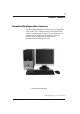
1 Product Features Standard Configuration Features The HP Compaq Microtower features may vary depending on the model. For a complete listing of the hardware and software installed in the computer, run the Diagnostics for Windows utility. Instructions for using this utility are provided in the Troubleshooting Guide on the Documentation and Diagnostics CD. Microtower Configuration Photos depicted may vary as per actual machine Hardware Reference Guide www.hp.
Product Features Front Panel Components Drive configuration may vary by model.
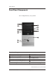
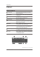
Product Features Rear Panel Components 1 2 3 4 5 6 7 8 9 10 11 12 Rear Panel Components Power Cord Connector 7 RJ-45 Network Connector . 2 Voltage Select Switch 8 Parallel Port Connector 3 PS/2 Mouse Connector 9 Monitor Connector 4 PS/2 Keyboard Connector 10 Headphone/Line-Out Connector 5 Universal Serial Bus (USB) 11 Audio/Line-In Connector 6 Serial Port Connector 12 Microphone Connector ! 1 Arrangement and number of connectors may vary by model.
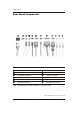
Product Features Keyboard Keyboard Components 1 Function Keys Perform special functions depending on the software application being used. 2 Editing Keys Includes the following: Insert, Home, Page Up, Delete, End, and Page Down. . 3 Status Lights Indicate the status of the computer and keyboard settings (Num Lock, Caps Lock, and Scroll Lock). 4 Numeric Keys Work like a calculator keypad. 5 Arrow Keys Used to navigate through a document or Web site.
Product Features Windows Logo Key Use the Windows Logo key in combination with other keys to perform certain functions available in the Windows operating system. Refer to the "Keyboard" section to identify the Windows Logo key. Windows Logo Key Functions Windows Logo Key Displays or hides the Start menu. Windows Logo Key + d Displays the Desktop. Windows Logo Key + m Minimizes all open applications. Shift + Windows Logo Key + m Undoes Minimize All. Windows Logo Key + e Launches My Computer.
Product Features Serial Number Location Each computer has a unique serial number and a product ID number that are located on the top cover of the computer. Keep these numbers available for use when contacting customer service for assistance. Serial Number and Product ID Location Photos depicted may vary as per actual machine Hardware Reference Guide www.hp.
2 Hardware Upgrades Serviceability Features The Microtower computer includes features that make it easy to upgrade and service. A Torx T-15 screwdriver is needed for many of the installation procedures described in this chapter. Warnings and Cautions Before performing upgrades be sure to carefully read all of the applicable instructions, cautions, and warnings in this guide.
Hardware Upgrades Removing the Computer Access Panel CAUTION: CAUTION: Before removing the computer access panel, ensure that the computer is turned off and that the power cord is disconnected from the electrical outlet. ! To remove the computer access panel: 1. Turn off the computer properly through the operating system and turn off any external devices. 2. Disconnect the power cord from the power outlet and the computer, and disconnect any external devices. 3. Remove the screw computer chassis.
Hardware Upgrades Removing the Front Bezel To remove the front bezel: 1. Turn off the computer properly through the operating system and turn off any external devices. 2. Disconnect the power cord from the power outlet and the computer, and disconnect any external devices. 3.
Hardware Upgrades Installing Additional Memory The computer comes with double data rate synchronous dynamic random access memory (DDR2-SDRAM) dual inline memory modules (DIMMs). DIMMs The memory sockets on the system board can be populated with up to four industry-standard DIMMs. These memory sockets are populated with at least one preinstalled DIMM. To achieve the maximum memory support, you can populate the system board with up to 8GB* of memory configured in a high-performing dual channel mode.
Hardware Upgrades Populating DIMM Sockets The system will automatically operate in single channel mode, dual channel Asymmetric mode, depending on how the DIMMs are installed. The system will operate in single channel mode if the DIMM sockets are populated in one channel only. The system will operate in dual channel Asymmetric mode if the total memory capacity of the DIMMs in Channel A is not equal to the total memory capacity of the DIMMs in Channel B.
Hardware Upgrades Installing DIMMs CAUTION: The memory module sockets have gold metal contacts. When upgrading the memory, it is important to use memory modules with gold metal contacts to prevent corrosion and/or oxidation resulting from having incompatible metals in contact with each other. CAUTION: Static electricity can damage the electronic components of the computer or optional cards.
Hardware Upgrades 5. Open both latches of the memory module socket memory module into the socket 2 1 , and insert the Installing a DIMM A memory module can be installed in only one way. Match the notch on the module with the tab on the memory socket. 6. Push the module down into the socket, ensuring that the module is fully inserted and properly seated. Make sure the latches are in the closed position 3 . 7. Repeat steps 5 and 6 to install any additional modules. 8. Replace the access panel.
Hardware Upgrades Removing a 5.25" Drive Bezel Blank If the computer was not shipped with a drive in the 5.25" option bay, the bay will be covered by a bezel blank. If you add a drive to the option bay, you must first remove the bezel blank. 1. Turn off the computer properly through the operating system and turn off any external devices. 2. Disconnect the power cord from the power outlet and the computer, and disconnect any external devices. 3. Remove the access panel and front bezel.
Hardware Upgrades Replacing or Upgrading a Drive The computer supports up to six drives that may be installed in various configurations. This section describes the procedure for replacing or upgrading the storage drives. A Torx screwdriver is needed to remove and install the guide screws and retainer screws on a drive. CAUTION: Make sure you back up your personal files on the hard drive to an external storage device, such as a CD, before removing the hard drive. Failure to do so will result in data loss.
Hardware Upgrades Locating Drive Positions 2 3 Drive Positions Photos depicted may vary as per actual machine Hardware Reference Guide www.hp.
Hardware Upgrades First 5.25-inch, half-height bays for optional drives Second 5.25-inch, half-height bays for optional drives 2 Two Nos. standard 3.5-inch, one-third height bays (1.44-MB diskette drive shown) 3 Two Nos. internal 3.5-inch, one-third height bays for hard drives Removing a Drive 1. Turn off the computer properly through the operating system and turn off any external devices. Disconnect the power cord from the power outlet and disconnect any external devices. . 2.
Hardware Upgrades 5. Hard disk is inserted or slide out from the back. Removing the Hard disk 6. ! Remove all the screws that secure the floppy drive in the bay. Slide the drive disk forward and out of the bay. WARNING: There may be sharp edges on the insides of the bay opening after the shield has been removed. Photos depicted may vary as per actual machine Hardware Reference Guide www.hp.
Hardware Upgrades Replacing a Drive CAUTION: To prevent loss of work and damage to the computer or drive: If you are inserting or removing a hard drive, shut down the operating system properly, then turn off the computer. Do not remove a hard drive while the computer is on or in standby mode. Before handling a drive, ensure that you are discharged of static electricity. While handling a drive, avoid touching the connector.
Hardware Upgrades 1. Slide the floppy drive into the drive bay, making sure to align the guide screws with the guide slots, until the drive snaps into place. 2 Sliding the Drives into the Drive Cage 2. Slide the optical drive into the drive bay, making sure to align the screw holes with the drive bays holes. Secure the Drive by tighten all two screws. Photos depicted may vary as per actual machine Hardware Reference Guide www.hp.
Hardware Upgrades 3. Slide in the hard disk from the front to back, making sure to align the screw holes with the drive bays holes. Secure the Drive by tighten all the screws at each bottom side 3 Sliding the Hard Drive into the Drive Cage Photos depicted may vary as per actual machine Hardware Reference Guide www.hp.
Hardware Upgrades Install Second Hard Disk A second Hard disk should be installed as per following 1 1. Secure hard drive in hard drive bay located in (as indicated by arrow 1 ). 2. Secure the second hard drive by tightening the 2 screws at bottom. Photos depicted may vary as per actual machine Hardware Reference Guide www.hp.
Hardware Upgrades 3. Connect one end of the data cables to the second hard drive as shown above. 4. The other end connect to the system board. Photos depicted may vary as per actual machine Hardware Reference Guide www.hp.
Hardware Upgrades 5. ! 6. Hardware Reference Guide Complete the procedure described in the "Reassembling the Computer" section of this chapter. Turn on the computer. If you replaced the primary hard drive, insert the Restore Plus! DVD to restore the operating system, software drivers, and/or any software applications that were preinstalled on the computer from HP. Follow the instructions in the guide included with the restore DVD.
Hardware Upgrades Removing or Installing an Expansion Card This computer has two PCI expansion slots, one PCI-Express x 1 & one PCI-Express x 16 slots PCI -E x16 Slot PCI -E x1 Slot PCI Slot PCI Slot Expansion Slot Locations Photos depicted may vary as per actual machine Hardware Reference Guide www.hp.
Hardware Upgrades To remove, replace, or add an expansion card. 1. Turn off the computer properly through the operating system and turn off any external devices. Disconnect the power cord from the power outlet and disconnect any external devices. 2. Remove the access panel and lay the computer on its side with the opening to internal parts where the access panel was located facing up. 3.
Hardware Upgrades 4. Before installing an expansion card, remove the expansion slot cover or the existing expansion card. a. If you are installing an expansion card in a vacant socket, remove the appropriate expansion slot cover on the back of the chassis. Pull the slot cover straight up from the socket then away from the inside of the chassis. Removing an Expansion Slot Cover Photos depicted may vary as per actual machine Hardware Reference Guide www.hp.
Hardware Upgrades b. If removing a standard PCI expansion card, hold the card at each end, and carefully rock it back and forth until the connectors pull free from the socket. Pull the expansion card straight up from the socket 1 then away from the inside of the chassis 2 to release it from the chassis frame. Be sure not to scrape the card against the other components. Removing an Expansion Card Photos depicted may vary as per actual machine Hardware Reference Guide www.hp.
Hardware Upgrades 5. If replacing or adding a new expansion card, hold the card just above the expansion slot on the system board then move the card toward the rear of the chassis 1 so that the bottom of the bracket on the card slides into the small slot on the chassis. Gently press the card straight down into the expansion slot on the system board 2 . Replacing or Adding an Expansion Card 6.
Hardware Upgrades 9. If you are replacing an expansion card, store the old card in the anti-static packaging that contained the new card. 10. While holding the expansion card bracket against the chassis, slide the slot cover lock down toward the expansion card brackets and slot covers 1 to secure them in place and replace the screw 2 that secures the slot cover lock. Securing the Expansion Cards and Slot Covers 11.
Hardware Upgrades Reassembling the Computer 1. Position the chassis in the upright position. Insert the four tabs at the bottom of the bezel 1 . Snap into the slots of the chassis. Align the two hooks on the top of the bezel into the rectangular holes on the chassis then rotate the bezel into the place 2 . Replacing the Front Bezel Photos depicted may vary as per actual machine Hardware Reference Guide www.hp.
Hardware Upgrades 2. Place the side access panel in the proper position on the chassis and slide it into place 1 . Ensure that the hole for the screw is aligned with the hole in the chassis and tighten the screw 2 . 12 2 Replacing the Side Access Panel ! 3. Reconnect the power cable to the computer and plug the cable into an electrical outlet. 4. Reconnect all peripheral devices to the computer.
3 ! Battery Replacement ! The battery that comes with the computer provides power to the realtime clock. When replacing the battery, use a battery equivalent to the battery originally installed in the computer. The computer comes with a 3-volt lithium coin cell battery. The lifetime of the lithium battery can be extended by plugging the computer into a live AC wall socket. The lithium battery is only used when the computer is NOT connected to AC power.
! CAUTION: Static electricity can damage the electronic components of the computer or optional equipment. Before beginning these procedures, ensure that you are discharged of static electricity by briefly touching a grounded metal object. 1. Turn off the computer properly through the operating system, then turn off any external devices. 2. Disconnect the power cord from the power outlet and disconnect any external devices. Then remove the computer access panel.
! Removing and Replacing a Coin Cell Battery After the battery has been replaced, use the following steps to complete this procedure. 5. Replace the computer access panel. 6. Plug in the computer and turn on power to the computer. 7. Reset the date and time, your passwords, and any special system setups, using Computer Setup. Refer to the Computer Setup (F10) Utility Guide on the Documentation and Diagnostics CD. Power Supply Notice ! WARNING: The power supply contains hazardous moving parts.
4 Security Lock Provisions Installing a Security Lock The security locks displayed on the below page can be used to secure the Microtower computer by putting a mechanical lock Mechanical Lock Installing a Mechanical Lock Chassis Intrusion Switch Photos depicted may vary as per actual machine Chassis Intrusion (CI) Switch, is a combination of hardware and software technology that can alert you when the computer cover or side panel has been removed.
5 Electrostatic Discharge A discharge of static electricity from a finger or other conductor may damage system boards or other static-sensitive devices. This type of damage may reduce the life expectancy of the device. Preventing Electrostatic Damage To prevent electrostatic damage, observe the following precautions: n n n n n Avoid hand contact by transporting and storing products in static-safe containers.
n ! n n Use heelstraps, toestraps, or bootstraps at standing workstations. Wear the straps on both feet when standing on conductive floors or dissipating floor mats. Use conductive field service tools. Use a portable field service kit with a folding static-dissipating work mat. If you do not have any of the suggested equipment for proper grounding, contact an HP authorized dealer, reseller, or service provider.
6 Computer Operating Guidelines, Routine Care and Shipping Preparation Computer Operating Guidelines and Routine Care Follow these guidelines to take care of the computer and monitor: n Operate the computer on a sturdy, level surface. Leave a 10.2cm (4-inch) clearance at the back of the system unit and above the monitor to permit the required airflow. n Never operate the computer with the cover or side panel removed. n Never restrict the airflow into the computer by blocking the front vents or air intake.
Optical Drive Precautions Be sure to observe the following guidelines while operating or cleaning the optical drive. Operation n n n Cleaning n n Safety Hardware Reference Guide Do not move the drive during operation. This may cause it to malfunction during reading. Avoid exposing the drive to sudden changes in temperature, as condensation may form inside the unit. If the temperature suddenly changes while the drive is on, wait at least one hour before you turn off the power.
Shipping Preparation Follow these suggestions when preparing to ship the computer: ! ! 1. Back up the hard drive files on PD discs, tape cartridges, CDs, or diskettes. Be sure that the backup media is not exposed to electrical or magnetic impulses while stored or in transit. The hard drive locks automatically when the system power is turned off. 2. Remove and store any program diskettes from the diskette drives. 3.
Computer Setup (F10) Utility Guide HP Compaq Business Desktop dx2480 Microtower Model March 2008 This guide provides instructions on how to use Computer Setup. This tool is used to reconfigure and modify computer default settings when new hardware is installed and for maintenance purposes.
Copyright 2008 Hewlett-Packard Development Company,L.P.The information contained herein is subject to change without notice. Microsoft, MS-DOS, Windows and Windows Vista are trademarks of Microsoft Corporation in the U.S. and other countries. The only warranties for HP products and services are set forth in the express warranty statements accompanying such products and services. Nothing herein should be construed as constituting an additional warranty.
Contents Computer Setup (F10) Utility Computer Setup (F10) Utilities ……………………………………………………….... Using Computer Setup (F10) Utilities …………………………………………….. System Information …….………………………………………………......…………. S/N …………………………………………………………………………………… Product Name ….……………………………………………………………………..... Set OwnerShip TAG [Press Enter] …………………………………………………….. OwnerShip TAG ……………………………………………………………………….. BIOS version …………………………...……………………………………………… BIOS Release Date ………………...…………………………………………………..
Contents First Boot Device ……………………………………………………………………… 7-6 Second Boot Device ………………………………………………………………....... 7-6 Third Boot Device……………………………...……………………………………… 7-6 Boot Other Device ...............................………………...........................… 7-6 APIC Mode…………………………………………………………………………… 7-6 Security option………………………………………………………………………… 7-6 F7(Diagnostic)Support………………………………………………………………. 7-6 F11 Prompt……………………………………………………………………………….
7 Computer Setup (F10) Utility Computer Setup (F10) Utilities n Use Computer Setup (F10) Utility to do the following; n Change factory default settings. n Set the system date and time. n Set,view,change,or verify the system configuration,including settings for processor, graphics, memory, audio, storage, communications,and input devices. n Modify the boot order of bootable devices such as hard drives, optical drives,orUSB flash media devices.
Computer Setup (F10) Utility Using Computer Setup (F10) Utilities Computer Setup can be accessed only by turning the computer on or restarting the system. To access the Computer Setup Utility menu, complete the following steps: ! 1. Turn on or restart the computer. If you are in Microsoft Windows, click Start > Shut Down > Restart. 2. As soon as the computer is turned on, press and hold the F10 key until you enter Computer Setup.
Computer Setup (F10) Utility Five action choices are listed on the Computer Setup Utility screen: n n n n n Load Default Settings Set Supervisor Password Set User Password Save Setting and Exit Exit Without Saving Use the arrow keys to select the appropriate heading, then press Enter. Use the arrow (up and down) keys to select the option you want, then press Enter. To return to the previous screen, press Esc. 4.
Computer Setup (F10) Utility Computer Setup Heading (Continued) Option Description System Information System S/N (view only) Product Name (view only) Set OwnerShip TAG [Press Enter] Enter ownership tag assigned by the owner.
Computer Setup (F10) Utility Computer Setup Heading (Continued) Option Description IDE Channel 0 Master This allows you to detect the device. IDE Channel 1 Master Also it allows you to set the IDE deviceto: • None • Auto(default) • Manual Access Mode This allows you to set the access mode to: • CHS • LBA • Large • Auto(Default) Also,this allows you to see the Hard disk information.
Computer Setup (F10) Utility Computer Setup Heading Advanced BIOS Features Advanced Chipset Features (Continued) Option Quick Power On Self Test Disables/enables the system to skip certain tests while booting. Enabling this feature decreases the time required to boot the system. Hard Disk Boot Priority Allows you to specify the order of hard drive devices. The first drive in the order has priority in boot sequence and is recognized as drive C (if any device attached).
Computer Setup (F10) Utility Computer Setup (Continued) Heading Option Description Advanced Chipset Features IGD DVMT/Fixed Memory This allows you to set memory size to: • 128MB • 256MB • MAX ! Integrated Peripherals USB Controller Disables/enables on board USB controller USB Legacy Support Disables/enables USB Keyboard support Azalia Audio Enable Disabled Onboard LAN Disables/enables onboard LAN controller. Onboard LAN Boot Disables/enables the boot ROM of the ROM onboard LAN chip.
Computer Setup (F10) Utility Computer Setup Heading ! Power Management Setup (Continued) Option ACPI Function Description Enables/disables ACPI functions. Changing this item can make the existing OS unusable. ACPI Suspend Type •S3 (STR) (View only) Restore On AC/Power Loss Allows you to select system powerloss behavior: •On •Off •Last State Resume On PCI PME Disables/enables Resume by PME Resume On PCIE PME Disables/enables Resume by PCIE PME Wake On by Ring Disables/enables Resume on Ring.
Computer Setup (F10) Utility Computer Setup (Continued) Heading Option Description Hard Ware Monitor Setup Reset Case Open Status Enabled/Disabled Case Opened (View Only) CPU Temperature (View Only) CPU Fan Speed (View Only) System Temperature (View Only) System Fan Speed (View Only) CPU Fan Fault Detect Enabled/Disabled System Fan Fault Detect Enabled /Disabled Allows you to reset computer setup to Factory Defaults Set Supervisor Password Allows you to establish a password to contro
Troubleshooting Guide HP Business Desktop dx2480 March 2008 This guide provides helpful hints and solutions for troubleshooting the above products as well as scenarios for possible hardware and software problems.
© Copyright 2008 Hewlett-Packard Development Company, L.P. The information contained herein is subject to change without notice. Microsoft, MS-DOS, Windows and Windows Vista are trademarks of Microsoft Corporation in the U.S. and other countries. The only warranties for HP products and services are set forth in the express warranty statements accompanying such products and services. Nothing herein should be construed as constituting an additional warranty.
1 Computer Diagnostic Features ! HP Insight Diagnostics HP Insight Diagnostics is included on CD with some computer models only. The HP Insight Diagnostics utility allows you to view information about the hardware configuration of the computer and perform hardware diagnostic tests on the subsystems of the computer. The utility simplifies the process of effectively identifying, diagnosing, and isolating hardware issues.
Computer Diagnostic Features Accessing HP Insight Diagnostics ! You must boot to the Documentation and Diagnostics CD, as described in the steps below, to access HP Insight Diagnostics. 1. While the computer is on, insert the Documentation and Diagnostics CD into an optical drive on the computer. 2. Shut down the operating system and turn off the computer. 3. Turn on the computer. The system will boot to the CD.
Computer Diagnostic Features Survey Tab The Survey tab displays important system configuration information. In the View section on the left side of the screen, you can select the Summary view to see limited configuration data or select the Advanced view to see all the data in the selected category. Regardless of whether you choose Advanced or Summary, the following categories of information are available on the Survey tab: All-Gives a listing of all categories of information about the computer.
Computer Diagnostic Features Test Tab The Test tab allows you to choose various parts of the system to test. You can also choose the type of test and testing mode. There are two test modes to choose from: n Interactive Mode-Provides maximum control over the testing process. The diagnostic software will prompt you for input during tests that require your interaction.You may also determine whether the test passed or failed. n Unattended Mode-Does not display prompts and requires no interaction.
Computer Diagnostic Features 5. Choose how you want the test to be executed, either Number of Loops or Total Test Time. When choosing to run the test over a specified number of loops, enter the number of loops to perform. If you desire to have the diagnostic test for a specified time period, enter the amount of time in minutes. 6. Click Begin Testing to start the test. The Status tab, which allows you to monitor the progress of the test, is automatically displayed during the testing process.
Computer Diagnostic Features Log Tab The Log tab contains two logs, a Test Log and an Error Log, each of which can be selected from the left side of the tab. The Test Log displays all tests that have been executed, the number of times of execution, the number of times the test failed, and the time it took to complete the test. The Clear Test Log button will clear the contents of the Test Log.
Computer Diagnostic Features ! 5. Print the information from the storage device used to save it. To exit HP Insight Diagnostics, click Exit in the upper right corner of the screen then remove the Documentation and Diagnostics CD from the optical drive. Downloading the Latest Version of HP Insight Diagnostics 1. 2. 3. 4. ! 5. 6. 7. 8. Go to www.hp.com. Click the Software & Driver Downloads link. Click the Download drivers and software radio button.
2 Troubleshooting ! Safety and Comfort WARNING: Misuse of the computer or failure to establish a safe and comfortable work environment may result in discomfort or serious injury. Refer to the Safety & Comfort Guide on the Documentation and Diagnostics CD and available at www.hp.com/ergo for more information on choosing a workspace and creating a safe and comfortable work environment.
Troubleshooting n If you are working on a network, plug another computer with a different cable into the network connection. There may be a problem with the network plug or cable. n If you recently added new hardware, remove the hardware and see if the computer functions properly. n If you recently installed new software, uninstall the software and see if the computer functions properly. n Boot the computer to the Safe Mode to see if it will boot without all of the drivers loaded.
Troubleshooting n Remove any hardware that was recently added to your system. ¦ Remove any software that was recently installed. n Run the Restore Plus! DVD. ! CAUTION: Running the Restore Plus! DVD will erase all data on the hard. drive For sales information and warranty upgrades (HP Care Pack Services), call your local authorized service provider or dealer.
Troubleshooting n Reconfigure the computer after installing a nonplug and play expansion board or other option. See "Solving Hardware Installation Problems" for instructions. n Be sure that all the needed device drivers have been installed. For example, if you are using a printer, you need a driver for that model printer. ¦ Remove all bootable media (diskette, CD, or USB device) from the system before turning it on.
Troubleshooting Solving General Problems You may be able to easily resolve the minor problems described in this section. If a problem persists and you are unable to resolve it yourself or if you feel uncomfortable about performing the operation, contact your HP authorized reseller or service provider. Problem Computer will not turn on. Cause Solution Cables to the external power source are unplugged.
Troubleshooting Problem Cause Solution Computer will not respond to USB keyboard or mouse. Computer is in standby mode. Press the power button to resume from standby mode. USB Keyboard does not respond/work Keyboard or mouse is not connected to computer. Connect keyboard and mouse cables to computer. System has locked up. Restart the computer. System USB Keyboard Restart the computer and support is not enabled in the press F10 to enter BIOS F10 BIOS setup. setup.
Troubleshooting Problem Poor performance is experienced (continued). Cause Solution Hard drive is full. Transfer data from the hard drive to create more space on the hard drive. Low on memory. Add more memory. Hard drive is fragmented. Defragment hard drive. Program previously accessed did not release reserved memory back to the system. Restart the computer. Virus resident on the hard drive. Run the virus protection program. Too many applications running. 1.
Troubleshooting Problem Blank screen (no video) (continued). Cause Solution You may have a screen blanking utility installed or energy saver features are enabled. Press any key or click the mouse button and, if set, type your password. Computer is in standby mode. Press the power button to resume from standby mode. CAUTION: When attempting to resume from standby mode, do not hold down the power button for more than four seconds.
Troubleshooting Solving Hardware Installation Problems You may need to reconfigure the computer when you add or remove hardware, such as an additional drive or expansion card. If you install a plug and play device, Windows XP Home/Professional/Vista will automatically recognize the device and configure the computer. If you install a nonplug and play device, you must reconfigure the computer after completing installation of the new hardware.
Troubleshooting Problem Computer will not start. Cause Wrong memory modules were used in the upgrade or memory modules were installed in the wrong location. Solution 1. Review the documentation that came with the system to determine if you are using the correct memory modules and to verify the proper installation. 2. Observe the beeps and LED lights on the front of the computer. See "Interpreting Diagnostic Lights and Audible Codes" to determine possible causes. 3.
Troubleshooting Diagnostic Front Panel LEDs and Audible Codes Activity Beeps Possible Cause Recommended Action Blue Power LED On. None Computer on. None Blue Power LED flashes every two seconds. None Computer in Press any key or move the Suspend to RAM mouse to wake the computer. mode (some models only) or normal Suspend mode. CPU Fan weak (RPM < 2 1000) or not turning, Display Warning message and Long Beep for 5 sec and shut down. Processor thermal 1.
Troubleshooting Diagnostic Front Panel LEDs and Audible Codes Activity System does not power on and LEDs are not flashing. Beeps None System gives an error Continuous message stating that beep for 5 “Error 912 - computer seconds cover or side panel has been removed. Make sure that any system access was authorized and press F1 to continue”. Possible Cause (Continued) Recommended Action System unable to power on. Press and hold the power button for less than 4 seconds.
Troubleshooting Restoring the Software ! The Windows operating system and software can be restored to the original state that they were when you purchased the computer by using the Restore Plus! DVD. See the documentation included with the Restore Plus! DVD for complete instructions on using this feature. In the event that you lose power during the initial operating system installation process, use the Restore Plus! DVD to install the operating system.