Hardware Reference Guide - dx7300 Microtower Model HP Compaq Business PC
© Copyright 2006 Hewlett-Packard Development Company, L.P. The information contained herein is subject to change without notice. Microsoft and Windows are trademarks of Microsoft Corporation in the U.S. and other countries. The only warranties for HP products and services are set forth in the express warranty statements accompanying such products and services. Nothing herein should be construed as constituting an additional warranty.
About This Book This guide provides basic information for upgrading this computer model. WARNING! Text set off in this manner indicates that failure to follow directions could result in bodily harm or loss of life. CAUTION Text set off in this manner indicates that failure to follow directions could result in damage to equipment or loss of information. NOTE Text set off in this manner provides important supplemental information.
iv About This Book ENWW
Table of contents 1 Product Features Standard Configuration Features ......................................................................................................... 1 Front Panel Components ..................................................................................................................... 2 Media Card Reader Components ......................................................................................................... 3 Rear Panel Components ................................
Padlock .............................................................................................................................. 42 Appendix D Electrostatic Discharge Preventing Electrostatic Damage ....................................................................................................... 43 Grounding Methods ............................................................................................................................
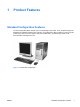
1 Product Features Standard Configuration Features The HP Compaq Microtower features may vary depending on the model. For a complete listing of the hardware and software installed in the computer, run the diagnostic utility (included on some computer models only). Instructions for using the utility are provided in the Troubleshooting Guide on the Documentation and Diagnostics CD.
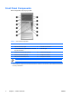
Front Panel Components Drive configuration may vary by model. Table 1-1 Front Panel Components 1 5.25-inch Optical Drives1 7 Optical Drive Eject Buttons 2 Optical Drive Activity Lights 8 Dual-State Power Button 3 3.5-inch Diskette Drive (optional) and 3.
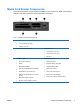
Media Card Reader Components The media card reader is an optional device available on some models only. Refer to the following illustration and table to identify the media card reader components. Table 1-2 Media Card Reader Components 1 2 3 ENWW SmartMedia/xD ● 3.
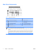
Rear Panel Components Table 1-3 Rear Panel Components 1 Power Cord Connector 7 Parallel Connector 2 PS/2 Mouse Connector (green) 8 Monitor Connector 3 PS/2 Keyboard Connector (purple) 9 Line-Out Connector for powered audio devices (green) 4 Universal Serial Bus (USB) 10 Line-In Audio Connector (blue) 5 Serial Connector 11 Microphone Connector (pink) 6 RJ-45 Network Connector NOTE Arrangement and number of connectors may vary by model.
Keyboard Table 1-4 Keyboard Components 1 ENWW 1 Function Keys Perform special functions depending on the software application being used. 2 Editing Keys Includes the following: Insert, Home, Page Up, Delete, End, and Page Down. 3 Status Lights Indicate the status of the computer and keyboard settings (Num Lock, Caps Lock, and Scroll Lock). 4 Numeric Keys Work like a calculator keypad. 5 Arrow Keys Used to navigate through a document or Web site.
Using the Windows Logo Key Use the Windows Logo key in combination with other keys to perform certain functions available in the Windows operating system. Refer to the Keyboard section to identify the Windows Logo key.
Special Mouse Functions Most software applications support the use of a mouse. The functions assigned to each mouse button depend on the software applications you are using. Serial Number Location Each computer has a unique serial number and product ID number that are located on the top cover of the computer. Keep these numbers available for use when contacting customer service for assistance.
8 Chapter 1 Product Features ENWW
2 Hardware Upgrades Serviceability Features The computer includes features that make it easy to upgrade and service. No tools are needed for most of the installation procedures described in this chapter. Warnings and Cautions Before performing upgrades be sure to carefully read all of the applicable instructions, cautions, and warnings in this guide.
Unlocking the Smart Cover Lock NOTE The Smart Cover Lock is an optional feature included on some models only. The Smart Cover Lock is a software-controllable cover lock, controlled by the setup password. This lock prevents unauthorized access to the internal components. The computer ships with the Smart Cover Lock in the unlocked position. For more information about locking the Smart Cover Lock, refer to the Desktop Management Guide on the Documentation and Diagnostics CD.
5. Use the Smart Cover FailSafe Key to remove the two tamper-proof screws that secure the Smart Cover Lock to the bottom of the chassis. Figure 2-1 Removing the Smart Cover Lock Screws 6. Remove the access panel. To reattach the Smart Cover Lock, secure the lock in place with the tamper-proof screws.
Removing the Computer Access Panel 1. Remove/disengage any security devices that prohibit opening the computer. 2. Remove all removable media, such as diskettes or compact discs, from the computer. 3. Turn off the computer properly through the operating system, then turn off any external devices. 4. Disconnect the power cord from the power outlet and disconnect any external devices.
Replacing the Computer Access Panel Place the access panel in the proper position on the chassis and slide it into place (1). Ensure that the hole for the thumbscrew is aligned with the hole in the chassis and tighten the thumbscrew (2).
Removing the Front Bezel 1. Remove/disengage any security devices that prohibit opening the computer. 2. Remove all removable media, such as diskettes or compact discs, from the computer. 3. Turn off the computer properly through the operating system, then turn off any external devices. 4. Disconnect the power cord from the power outlet and disconnect any external devices.
Replacing the Front Bezel Position the chassis in the upright position. Insert the two hooks on the right side of the bezel and the one hook at the top of the bezel (1) into the rectangular holes on the chassis then rotate the bezel into place (2) so that the three tabs on the left side of the bezel snap into the slots on the chassis.
Installing Additional Memory The computer comes with double data rate 2 synchronous dynamic random access memory (DDR2SDRAM) dual inline memory modules (DIMMs). DIMMs The memory sockets on the system board can be populated with up to four industry-standard DIMMs. These memory sockets are populated with at least one preinstalled DIMM. To achieve the maximum memory support, you can populate the system board with up to 8 GB of memory configured in a highperforming dual channel mode.
Populating DIMM Sockets There are four DIMM sockets on the system board, with two sockets per channel. The sockets are labeled XMM1, XMM2, XMM3, and XMM4. Sockets XMM1 and XMM2 operate in memory channel A. Sockets XMM3 and XMM4 operate in memory channel B.
should be populated with the two 512MB DIMMs. With this configuration, 2 GB will run as dual channel and 256 MB will run as single channel. ● In any mode, the maximum operational speed is determined by the slowest DIMM in the system. Installing DIMMs CAUTION You must disconnect the power cord before adding or removing memory modules. Regardless of the power-on state, voltage is always supplied to the memory modules as long as the computer is plugged into an active AC outlet.
7. Open both latches of the memory module socket (1), and insert the memory module into the socket (2). Figure 2-7 Installing a DIMM NOTE A memory module can be installed in only one way. Match the notch on the module with the tab on the memory socket. A DIMM must occupy the black XMM1 socket. For maximum performance, populate the sockets so that the memory capacity is spread as equally as possible between Channel A and Channel B. Refer to Populating DIMM Sockets for more information. 8.
Removing or Installing an Expansion Card The computer has two standard PCI expansion slots that can accommodate an expansion card up to 17.46 cm (6.875 inches) in length. The computer also has one PCI Express x1 expansion slot and one PCI Express x16 expansion slot.
5. Remove the computer access panel. CAUTION After removing the access panel, look for the LED on the system board to the right of the DIMM sockets. If the LED is illuminated, the system still has power. Turn off the computer and remove the power cord before proceeding. 6. Locate the correct vacant expansion socket on the system board and the corresponding expansion slot on the back of the computer chassis. 7.
NOTE Before removing an installed expansion card, disconnect any cables that may be attached to the expansion card. a. If you are installing an expansion card in a vacant socket, remove the appropriate expansion slot cover on the back of the chassis. Pull the slot cover straight up then away from the inside of the chassis.
b. If you are removing a standard PCI card, hold the card at each end, and carefully rock it back and forth until the connectors pull free from the socket. Pull the expansion card straight up from the socket (1) then away from the inside of the chassis (2) to release it from the chassis frame. Be sure not to scrape the card against the other components. Figure 2-11 Removing a Standard PCI Expansion Card c.
9. Store the removed card in anti-static packaging. 10. If you are not installing a new expansion card, install an expansion slot cover to close the open slot. CAUTION After removing an expansion card, you must replace it with a new card or expansion slot cover for proper cooling of internal components during operation. 11.
12. While holding the expansion card bracket against the chassis, slide the slot cover lock down toward the expansion card brackets and slot covers (1) to secure them in place and replace the thumbscrew (2) that secures the slot cover lock. Figure 2-14 Securing the Expansion Cards and Slot Covers 13. Connect external cables to the installed card, if needed. Connect internal cables to the system board, if needed. 14. Replace the computer access panel. 15. Reconnect the power cord and turn on the computer.
Drive Positions Figure 2-15 Drive Positions 1 Two 5.25-inch external drive bays for optional drives (optical drives shown) 2 Two 3.5-inch external drive bays for optional drives (diskette drives shown) 3 Two 3.5-inch internal hard drive bays To verify the type and size of the storage devices installed in the computer, run Computer Setup. Refer to the Computer Setup (F10) Utility Guide on the Documentation and Diagnostics CD for more information.
Installing Additional Drives The computer supports up to five drives that may be installed in various configurations. When installing additional drives, follow these guidelines: ● The primary Serial ATA (SATA) hard drive must be connected to the dark blue SATA connector on the system board labeled SATA0. ● Connect the first SATA optical drive to the white SATA connector on the system board labeled SATA1.
Removing a Drive from a Drive Bay CAUTION All removable media should be taken out of a drive before removing the drive from the computer. NOTE Before you remove the old hard drive, be sure to back up the data from the old hard drive so that you can transfer the data to the new hard drive.
b. If you are removing a diskette drive, disconnect the data cable (1) and power cable (2) from the back of the drive. Figure 2-17 Disconnecting the Diskette Drive Cables c. If you are removing a hard drive, disconnect the power cable (1) and data cable (2) from the back of the drive.
d. If your are removing a media card reader, disconnect the USB cable from the PCI card. Figure 2-19 Disconnecting the Media Card Reader Cable 8. A latch drive bracket with release tabs secures the drives in the drive bay. Lift the release tab on the latch drive bracket (1) for the drive you want to remove, then slide the drive from its drive bay (2). Figure 2-20 Removing the Drives 9. 30 Remove the four guide screws (two on each side) from the old drive.
Installing a Drive NOTE An optical drive is a CD-ROM, CD-R/RW, DVD-ROM, DVD+R/RW, or CD-RW/DVD Combo drive. A 3.5-inch drive may be a diskette drive or a media card reader. The system does not support Parallel ATA (PATA) hard drives or optical drives. 1. Install the four guide screws (two on each side) that were removed from the old drive into the new drive. The screws help guide the drive into its proper position in the bay.
3. Connect the power and data cables to the drive as indicated in the following illustrations. a. If you are installing an optical drive, connect the power cable (1) and data cable (2) to the back of the drive. Figure 2-22 Connecting the Optical Drive Cables b. If you are installing a diskette drive, connect the data cable (1) and power cable (2) to the back of the drive.
c. If you are installing a hard drive, connect the power cable (1) and data cable (2) to the back of the drive. Figure 2-24 Connecting the Hard Drive Cables 4. If you are installing a new drive, connect the opposite end of the data cable to the appropriate system board connector. NOTE If your system has only one SATA hard drive, you must connect the hard drive data cable to the dark blue connector labeled SATA0 to avoid any hard drive performance problems.
34 Chapter 2 Hardware Upgrades ENWW
A Specifications Desktop Dimensions Height 14.5 in 36.8 cm Width 6.88 in 17.5 cm Depth 16.5 in 42.0 cm 23.8 lb 10.82 kg Operating 50° to 95°F 10° to 35°C Nonoperating -22° to 140°F -30° to 60°C Operating 10-90% 10-90% Nonoperating (38.
Rated Input Current (maximum)1 1 36 6A @ 100 VAC 3A @ 200 VAC This system utilizes an active power factor corrected power supply. This allows the system to pass the CE mark requirements for use in the countries of the European Union. The active power factor corrected power supply also has the added benefit of not requiring an input voltage range select switch.
B Battery Replacement The battery that comes with the computer provides power to the real-time clock. When replacing the battery, use a battery equivalent to the battery originally installed in the computer. The computer comes with a 3-volt lithium coin cell battery. WARNING! The computer contains an internal lithium manganese dioxide battery. There is a risk of fire and burns if the battery is not handled properly. To reduce the risk of personal injury: Do not attempt to recharge the battery.
5. Remove the computer access panel. CAUTION After removing the access panel, look for the LED on the system board to the right of the DIMM sockets. If the LED is illuminated, the system still has power. Turn off the computer and remove the power cord before proceeding. 6. Locate the battery and battery holder on the system board. NOTE On some computer models, it may be necessary to remove an internal component to gain access to the battery. 7.
b. To insert the new battery, slide one edge of the replacement battery under the holder’s lip with the positive side up. Push the other edge down until the clamp snaps over the other edge of the battery (2). Figure B-2 Removing and Replacing a Coin Cell Battery (Type 2) Type 3 a. Pull back on the clip (1) that is holding the battery in place, and remove the battery (2). b. Insert the new battery and position the clip back into place.
40 Appendix B Battery Replacement ENWW
C External Security Devices NOTE For information on data security features, refer to the Computer Setup (F10) Utility Guide and the Desktop Management Guide on the Documentation and Diagnostics CD and the HP ProtectTools Security Manager Guide (some models) at http://www.hp.com. Installing a Security Lock The security locks displayed below and on the following page can be used to secure the computer.
Padlock Figure C-2 Installing a Padlock 42 Appendix C External Security Devices ENWW
D Electrostatic Discharge A discharge of static electricity from a finger or other conductor may damage system boards or other static-sensitive devices. This type of damage may reduce the life expectancy of the device. Preventing Electrostatic Damage To prevent electrostatic damage, observe the following precautions: ● Avoid hand contact by transporting and storing products in static-safe containers.
44 Appendix D Electrostatic Discharge ENWW
E Computer Operating Guidelines, Routine Care and Shipping Preparation Computer Operating Guidelines and Routine Care Follow these guidelines to properly set up and care for the computer and monitor: ENWW ● Keep the computer away from excessive moisture, direct sunlight, and extremes of heat and cold. ● Operate the computer on a sturdy, level surface. Leave a 10.2-cm (4-inch) clearance on all vented sides of the computer and above the monitor to permit the required airflow.
Optical Drive Precautions Be sure to observe the following guidelines while operating or cleaning the optical drive. Operation ● Do not move the drive during operation. This may cause it to malfunction during reading. ● Avoid exposing the drive to sudden changes in temperature, as condensation may form inside the unit. If the temperature suddenly changes while the drive is on, wait at least one hour before you turn off the power. If you operate the unit immediately, it may malfunction while reading.
Index A access panel locking and unlocking removing 12 replacing 13 audio connectors 2, 4 10, 41 B backup and recovery 33 battery replacement 37 C computer operating guidelines 45 connecting drive cables 27 D DIMMs.
computer access panel 12 drives from drive bay 28 expansion card 20 expansion slot cover 22 front bezel 14 media card reader 28 PCI card 23 PCI Express card 23 Smart Cover Lock 10 S security cable lock 41 padlock 42 Smart Cover Lock 10 serial connector 4 serial number location 7 shipping preparation 46 Smart Cover Lock 10 specifications computer 35 memory 16 U unlocking access panel USB ports front panel 2 rear panel 4 10, 41 V ventilation guidelines 45 W Windows Logo key 6 48 Index ENWW