Hardware Reference Guide HP Compaq dx7400 Series—Microtower Models
© Copyright 2007 Hewlett-Packard Development Company, L.P. The information contained herein is subject to change without notice. Microsoft, Windows, and Windows Vista are either trademarks or registered trademarks of Microsoft Corporation in the United States and/or other countries. The only warranties for HP products and services are set forth in the express warranty statements accompanying such products and services. Nothing herein should be construed as constituting an additional warranty.
About This Book This guide provides basic information for upgrading this computer model. WARNING! Text set off in this manner indicates that failure to follow directions could result in bodily harm or loss of life. CAUTION: Text set off in this manner indicates that failure to follow directions could result in damage to equipment or loss of information. NOTE: Text set off in this manner provides important supplemental information.
iv About This Book ENWW
Table of contents 1 Product Features Standard Configuration Features ......................................................................................................... 1 Serviceability Features ......................................................................................................................... 1 Keyboard .............................................................................................................................................. 2 Using the Windows Logo Key .....
vi ENWW
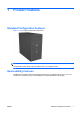
1 Product Features Standard Configuration Features Figure 1-1 HP Compaq dx7400 Series Microtower NOTE: The drive configuration shown above may be different than your computer model. The illustration shown above may look different than your computer model. Serviceability Features The Microtower computer includes features that make it easy to upgrade and service. A Torx T-15 screwdriver is needed for many of the installation procedures described in this chapter.
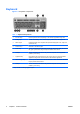
Keyboard Figure 1-2 Keyboard Components Table 1-1 Keyboard Components 1 2 1 Function Keys Perform special functions depending on the software application being used. 2 Editing Keys Includes the following: Insert, Home, Page Up, Delete, End, and Page Down. 3 Status Lights Indicate the status of the computer and keyboard settings (Num Lock, Caps Lock, and Scroll Lock). 4 Numeric Keys Work like a calculator keypad. 5 Arrow Keys Used to navigate through a document or Web site.
Using the Windows Logo Key Use the Windows Logo key in combination with other keys to perform certain functions available in the Windows operating system. Refer to Keyboard on page 2 to identify the Windows Logo key. Table 1-2 Windows Logo Key Functions The following Windows Logo Key functions are available in Microsoft Windows XP and Microsoft Windows Vista.
Warnings and Cautions Before performing upgrades be sure to carefully read all of the applicable instructions, cautions, and warnings in this guide. WARNING! To reduce the risk of personal injury from electrical shock, rotating fans, hot surfaces, and/ or fire: Disconnect the power cord from the wall outlet and allow the internal system components to cool before touching. Do not plug telecommunications or telephone connectors into the network interface controller (NIC) receptacles.
2 Hardware Upgrades Removing the Computer Access Panel and Front Bezel 1. Remove/disengage any security devices that prohibit opening the computer. 2. Remove all removable media, such as diskettes or compact discs, from the computer. 3. Turn off the computer properly through the operating system, then turn off any external devices. 4. Disconnect the power cord from the power outlet and the computer (1), and disconnect any external devices.
7. To remove the front bezel, pull outward on all three tabs on the left side of the bezel (1) then rotate the bezel off the chassis (2), beginning with the left side then the right side. Figure 2-2 Removing the Front Bezel NOTE: To replace the front bezel, insert the three hooks on the right side of the bezel into the rectangular holes on the chassis then rotate the bezel into place so that the catches on the three tabs on the left side of the bezel snap into place on the chassis.
Removing a 5.25" Drive Bezel Blank If the computer was not shipped with a drive in the 5.25" option bay, the bay will be covered by a bezel blank. If you add a drive to the option bay, you must first remove the bezel blank. 1. Remove/disengage any security devices that prohibit opening the computer. 2. Remove all removable media, such as diskettes or compact discs, from the computer. 3. Turn off the computer properly through the operating system, then turn off any external devices. 4.
Removing a 3.5" Drive Bezel Blank If the computer was not shipped with a device in the 3.5" bay, the bay will be covered by a bezel blank. If you install a device in the 3.5" bay, you must first remove the bezel blank. 1. Remove/disengage any security devices that prohibit opening the computer. 2. Remove all removable media, such as diskettes or compact discs, from the computer. 3. Turn off the computer properly through the operating system, then turn off any external devices. 4.
Installing Additional Memory The computer comes with double data rate 2 synchronous dynamic random access memory (DDR2SDRAM) dual inline memory modules (DIMMs). DIMMs The memory sockets on the system board can be populated with up to four industry-standard DIMMs. These memory sockets are populated with at least one preinstalled DIMM. The sockets are labeled DIMM1, DIMM2, DIMM3, and DIMM4. To achieve the maximum memory support, you can populate the system board with up to 4GB (4 x 1GB) of memory.
3. Turn off the computer properly through the operating system, then turn off any external devices. 4. Disconnect the power cord from the power outlet and the computer, and disconnect any external devices. WARNING! You must disconnect the power cord and wait approximately 30 seconds for the power to drain before adding or removing memory modules. Regardless of the power-on state, voltage is always supplied to the memory modules as long as the computer is plugged into an active AC outlet.
Installing an Expansion Card The computer has one standard PCI expansion slot that can accommodate an expansion card up to 17.46 cm (6.875 inches) in length. The computer also has two PCI Express x1 expansion slots and one PCI Express x16 expansion slot. 1. Remove/disengage any security devices that prohibit opening the computer. 2. Remove all removable media, such as diskettes or compact discs, from the computer. 3.
8. Hold the expansion card just above the expansion socket on the system board then move the card toward the rear of the chassis so that the bottom of the bracket on the card slides into the small slot on the chassis. Press the card straight down into the expansion socket on the system board. Figure 2-7 Installing an Expansion Card NOTE: When installing an expansion card, press firmly on the card so that the whole connector seats properly in the expansion card slot. 9.
Replacing or Upgrading a Drive The computer supports up to five drives that may be installed in various configurations. This section describes the procedure for replacing or upgrading the storage drives. A Torx T-15 screwdriver is needed to remove and install the guide screws and retainer screws on a drive. Locating Drive Positions NOTE: The drive configuration shown below may be different than your computer model. Figure 2-8 Drive Positions 1 ENWW 1 External 5.
System Board Drive Connections Follow the guidelines in the illustration and table below when connecting drives to the system board.
Removing a 5.25" Optical Drive 1. Remove/disengage any security devices that prohibit opening the computer. 2. Remove all removable media, such as diskettes or compact discs, from the computer. 3. Turn off the computer properly through the operating system, then turn off any external devices. 4. Disconnect the power cord from the power outlet and the computer, and disconnect any external devices.
Removing a 3.5" Media Card Reader or Diskette Drive The 3.5" external drive bay may be populated with a diskette drive or a media card reader. The removal procedure is the same for both devices. 1. Remove/disengage any security devices that prohibit opening the computer. 2. Remove all removable media, such as diskettes or compact discs, from the computer. 3. Turn off the computer properly through the operating system, then turn off any external devices. 4.
NOTE: If you are installing a drive in the external 3.5" drive bay for the first time, use a flatblade screwdriver to pry out the metal shield covering the bay. There are a total of eight extra guide/retainer screws on the front of the chassis behind the bezel. Four have 6-32 standard threads and four have M3 metric threads. Standard screws are used for hard drives and have a silver finish. Metric screws are used for all other drives and have a black finish.
Installing a Security Lock An optional security lock can be installed on the rear panel of the computer to provide physical computer security. Figure 2-13 Installing a Security Lock NOTE: The security lock slot may be in a different location on your computer model.
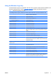
A Specifications Table A-1 Specifications Desktop Dimensions Height 13.9 in 35.3 cm Width 6.89 in 17.5 cm Depth 16.38 in 41.6 cm Approximate Weight 21.16 lb 9.6 kg Operating 50° to 95°F 10° to 35°C Nonoperating -22° to 140°F -30° to 60°C Temperature Range NOTE: Operating temperature is derated 1.0° C per 300 m (1000 ft) to 3000 m (10,000 ft) above sea level; no direct sustained sunlight. Maximum rate of change is 10° C/Hr.
B Battery Replacement The battery that comes with the computer provides power to the real-time clock. When replacing the battery, use a battery equivalent to the battery originally installed in the computer. The computer comes with a 3-volt lithium coin cell battery. WARNING! The computer contains an internal lithium manganese dioxide battery. There is a risk of fire and burns if the battery is not handled properly. To reduce the risk of personal injury: Do not attempt to recharge the battery.
7. Depending on the type of battery holder on the system board, complete the following instructions to replace the battery. Type 1 a. Lift the battery out of its holder. Figure B-1 Removing a Coin Cell Battery (Type 1) b. Slide the replacement battery into position, positive side up. The battery holder automatically secures the battery in the proper position. Type 2 a. To release the battery from its holder, squeeze the metal clamp that extends above one edge of the battery.
b. Insert the new battery and position the clip back into place. Figure B-3 Removing a Coin Cell Battery (Type 3) NOTE: After the battery has been replaced, use the following steps to complete this procedure. 8. Replace the computer access panel. 9. Plug in the computer and turn on power to the computer. 10. Reset the date and time, your passwords, and any special system setups using Computer Setup. Refer to the Computer Setup (F10) Utility Guide. 11.
C Computer Operating Guidelines, Routine Care and Shipping Preparation Computer Operating Guidelines and Routine Care Follow these guidelines to properly set up and care for the computer and monitor: ENWW ● Keep the computer away from excessive moisture, direct sunlight, and extremes of heat and cold. ● Operate the computer on a sturdy, level surface. Leave a 10.2-cm (4-inch) clearance on all vented sides of the computer and above the monitor to permit the required airflow.
Optical Drive Precautions Be sure to observe the following guidelines while operating or cleaning the optical drive. Operation ● Do not move the drive during operation. This may cause it to malfunction during reading. ● Avoid exposing the drive to sudden changes in temperature, as condensation may form inside the unit. If the temperature suddenly changes while the drive is on, wait at least one hour before you turn off the power. If you operate the unit immediately, it may malfunction while reading.
D Electrostatic Discharge A discharge of static electricity from a finger or other conductor may damage system boards or other static-sensitive devices. This type of damage may reduce the life expectancy of the device. Preventing Electrostatic Damage To prevent electrostatic damage, observe the following precautions: ● Avoid hand contact by transporting and storing products in static-safe containers.
Index A access panel installing 5 removing 5 B battery replacement 20 bezel blank, installing 3.5” 8 5.25” 7 bezel blank, removing 3.5” 8 5.