
HP ProLiant Cluster HA/F500 for MA8000 Enhanced DT Supplement Guide

Cluster Installation
Connecting Fiber Optic Cables Between the Controllers and
Switches
To establish fiber optic connections:
1. Connect a multimode fiber optic cable from port 1 of the top controller to port 2
of the top Fibre Channel switch.
2. Connect a second multimode fiber optic cable from port 2 of the top controller to
port 4 of the top Fibre Channel switch.
3. Connect a third multimode fiber optic cable from port 1 of the bottom controller
to port 2 of the bottom Fibre Channel switch.
4. Connect a fourth multimode fiber optic cable from port 2 of the bottom controller
to port 4 of the bottom Fibre Channel switch.
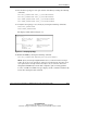
IMPORTANT: If “PORT_1_TOPOLOGY = FABRIC (point-to-point)” is displayed, it
indicates a switch configuration error. Consult the switch documentation to correct this
problem.
NOTE: A green LED indicator on the switch illuminates as soon as the cable is inserted
at both ends. This verifies that there is a good connection.
2-16 HP ProLiant Cluster HA/F500 for MA8000 Enhanced DT Supplement Guide
HP CONFIDENTIAL
Writer: Bill Akers File Name: c-ch2 Cluster Installation
Codename: Chargers II Part Number: 324547-001 Last Saved On: 4/7/03 10:32 AM