
HP ProLiant Cluster HA/F500 for MA8000 Enhanced DT Supplement Guide

Cluster Installation
Connecting the Target Site to the External Fiber Link
Locate the connection points linking the target site to the initiator site. Look for either
a fiber optic cable connector or a patch panel to insert the cable.
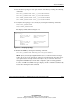
To connect the target site to the external fiber link:
1. Connect a single-mode fiber optic cable pair from port 6 of the top switch to
one connection point.
2. Connect another single-mode fiber optic cable pair from port 6 of the bottom
switch to the other connection point.
The target site is now physically linked to the initiator site.
Connecting the Target Site to the ATM Link
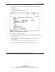
Locate the connection points linking the target site to the initiator site. To connect the
target site to the ATM link:
1. Connect a multimode fiber optic cable from port 6 of the first switch to
PCI number 1 on the first Open Systems Gateway (OSG) box.
2. Connect a multimode fiber optic cable from port 6 of the second switch to
PCI number 1 on the second OSG box.
Refer to the SANworks Data Replication Manager Over an ATM Link Application
Note for information on completing the connection to the ATM link.
Configuring the Host at the Target Site
Configure the target site host to complete the target site configuration.
Installing the Host Bus Adapters and Drivers
Install two HBAs in each host system to run DRM. Refer to the HBA documentation
for installation information.
HP ProLiant Cluster HA/F500 for MA8000 Enhanced DT Supplement Guide 2-17
HP CONFIDENTIAL
Writer: Bill Akers File Name: c-ch2 Cluster Installation
Codename: Chargers II Part Number: 324547-001 Last Saved On: 4/7/03 10:32 AM