
Compaq ProLiant Cluster HA/F500 for Enterprise Virtual Array Quick Installation & Configuration Poster
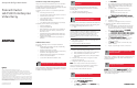

Host A
Interconnect
LAN
FCA
SA
Top FC Switch
HSV Controller AFP1
FP1
FP2
FP2
HSV Controller B
Storage
Subsystem
Bottom FC Switch
S1 S2 S1 S2
FCA FCA FCA
Host B
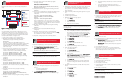
Zoning
Top FC Switch
"Controllerzone"
SA
HSV Controller A FP1
HSV Controller B FP2
"Clusterzone"
Host A S1
Host B S1
HSV Controller A FP1
HSV Controller B FP2
Zoning
Bottom FC Switch
"Clusterzone"
Host A S2
Host B S2
HSV Controller B FP1
HSV Controller B FP2
7
9
8
10
11
12
13
Creating the Storage System
and Virtual Disks
1. Initialize the storage with a descriptive name. Decide how
to configure the disk groups during the initialization
process. Choose to create either multiple disk groups or a
single disk group.
2. Enter a license key if the management appliance requests
one.
3. Configure disk groups.
4. Set the storage system time.
5. Add the hosts to the storage system:
a. Select
Hosts.Hosts.
Hosts.Hosts.
Hosts.
b. Click
Add a HostAdd a Host
Add a HostAdd a Host
Add a Host
..
..
.
c. Enter a host name.
d. Enter the correct IP address.
IMPIMP
IMPIMP
IMP
OROR
OROR
OR
TT
TT
T
ANAN
ANAN
AN
TT
TT
T
::
::
: If the wrong IP address is entered and saved at the
end of this procedure, it cannot be changed without deleting and
recreating the host.
e. Click
NeNe
NeNe
Ne
xtxt
xtxt
xt
Step Step
Step Step
Step
..
..
.
f. Enter an adapter port WWN. Use the information in
the worksheet in Appendix B of the HA/F500 setup
and installation guide to correctly identify which FCA
card is located in each server, or use the
lputilnlputiln
lputilnlputiln
lputiln
tt
tt
t
utility. Select the correct WWN from the list.
g. Select
MicrMicr
MicrMicr
Micr
osooso
osooso
oso
ff
ff
f
tt
tt
t
WW
WW
W
indowindow
indowindow
indow
ss
ss
s as the operating system.
h. Click
NeNe
NeNe
Ne
xtxt
xtxt
xt
Step Step
Step Step
Step
..
..
.
i. Click
FF
FF
F
inish,inish,
inish,inish,
inish,
OK. OK.
OK. OK.
OK.
j. Click
Add a PAdd a P
Add a PAdd a P
Add a P
oror
oror
or
tt
tt
t
..
..
.
k. Select the second FCA from the list.
l. Click
FF
FF
F
inish,inish,
inish,inish,
inish,
OK. OK.
OK. OK.
OK.
m. Repeat steps a through l for the second host.
6. Create the virtual disk drives:
a. Select Virtual Disks.
b. Click
CrCr
CrCr
Cr
eaea
eaea
ea
te te
te te
te
VD FVD F
VD FVD F
VD F
am.am.
am.am.
am.
c. Assign the virtual disk name.
d. Select a Vraid.
e. Select the correct Prefer path/mode.
PP
PP
P
aa
aa
a
th A-Fth A-F
th A-Fth A-F
th A-F
ailoailo
ailoailo
ailo
vv
vv
v
erer
erer
er
onlyonly
onlyonly
only or
PP
PP
P
aa
aa
a
th B-Fth B-F
th B-Fth B-F
th B-F
ailoailo
ailoailo
ailo
vv
vv
v
er onlyer only
er onlyer only
er only are the only options
supported for clustering. Set a preferred controller for
each virtual disk drive for load balancing.
f. Click
FF
FF
F
inish,inish,
inish,inish,
inish,
OK. OK.
OK. OK.
OK.
g. Repeat steps a through f to create the virtual disks
needed according to the number of LUNs you will
have.
7. Present the virtual disk drives to both of the hosts in the
cluster:
a. Select a physical disk.
b. Click
PrPr
PrPr
Pr
esenesen
esenesen
esen
tt
tt
t
..
..
.
c. Select a host.
d. Click
FF
FF
F
inish,inish,
inish,inish,
inish,
OK. OK.
OK. OK.
OK.
e. Click
PrPr
PrPr
Pr
esenesen
esenesen
esen
tt
tt
t
..
..
.
f. Select the second host.
g. Click
FF
FF
F
inish,inish,
inish,inish,
inish,
OK. OK.
OK. OK.
OK.
9. Create the cluster zone on the switch by using the
following command:
zonecreate "ClusterZoneName",
"HSVControllerAPortAlias;
HSVControllerBPortAlias;HostAConnectionAlias;
HostBConnectionAlias"
10.Verify the cluster zone by using the following command:
zoneshow
11.Create a zone configuration to integrate the switch cluster
zone and the controller zone by using the following
commands:
cfgcreate "ZoneConfigurationName",
"ClusterZoneName;ControllerZoneName"
cfgsave
cfgenable "ZoneConfigurationName"
A zone configuration is a set of one or more zones. When
zoning is enabled, one zone configuration is in effect. When
a zone configuration is in effect, all zones that are members
of that configuration are valid.
12.Check the created configuration by using the following
command:
zoneshow
13.Type in reboot to restart the switch that was just
configured.
14.Repeat the zoning steps for the second switch. Skip
the steps used to create the controller zone; there will
notnot
notnot
not
be a controller zone on the second switch.
15.Repeat the zoning steps for the remaining clusters.
Downloading the Latest FCA Driver
Perform the following steps before presenting the disk drives:
1. Verify the FCA driver version installed on your system.
2. Go to
ww
ww
w
ww
ww
w
ww
ww
w
.c.c
.c.c
.c
ompaq.compaq.c
ompaq.compaq.c
ompaq.c
om/om/
om/om/
om/
prpr
prpr
pr
oducoduc
oducoduc
oduc
ts/ts/
ts/ts/
ts/
serser
serser
ser
vv
vv
v
ers/ers/
ers/ers/
ers/
prpr
prpr
pr
olianolian
olianolian
olian
tstortstor
tstortstor
tstor
agag
agag
ag
ee
ee
e
//
//
/
adapters/adapters/
adapters/adapters/
adapters/ and check for the latest Fibre
Channel Host Bus Adapter driver version supported.
IMPIMP
IMPIMP
IMP
OROR
OROR
OR
TT
TT
T
ANAN
ANAN
AN
TT
TT
T: Skip the following step if you already have the latest
FCA driver installed on your system.
3. Download the latest FCA driver update utility and install
the update utility on each server, one server at a time.
Logging On to the Storage System
1. Log on to the management appliance from any network
browser.
- User name=administrator
- Password=administrator
2. Select
RR
RR
R
esouresour
esouresour
esour
ce Managce Manag
ce Managce Manag
ce Manag
erer
erer
er
,,
,,
,
Elemen Elemen
Elemen Elemen
Elemen
tt
tt
t
Manag Manag
Manag Manag
Manag
erer
erer
er
,,
,,
,
HS HS
HS HS
HS
VV
VV
V
ElemenElemen
ElemenElemen
Elemen
tt
tt
t
Manag Manag
Manag Manag
Manag
erer
erer
er to launch the HSV Element Manager.
Zoning
Figure 1 shows a cluster cross-cable zoning configuration
setup.
FF
FF
F
igurigur
igurigur
igur
e 1e 1
e 1e 1
e 1
::
::
:
Z Z
Z Z
Z
oning coning c
oning coning c
oning c
onfiguronfigur
onfiguronfigur
onfigur
aa
aa
a
tiontion
tiontion
tion
Use the following steps and Telnet commands to create a
controller zone, cluster zones, and a configuration zone. The
SAN switch has a graphical user interface (GUI) that can also
be used to create zoning. Refer to the switch documentation
for detailed information on using the GUI.
1. Telnet to the IP address of one of the switches.
2. Display the World Wide Names (WWNs) and port
information by using the following command:
switchshow
Record the complete 16-digit WWN and the port
information in the worksheet in Appendix B of the ProLiant
Cluster HA/F500 for Enterprise Virtual Array Setup and
Installation Guide. The information in the worksheet will be
used in later steps.
3. Create aliases for the controller zone. The controller zone
consists of the SAN Appliance connections and the
controller connections. Use the following commands:
alicreate "SANApplianceAlias", "WWN"
alicreate "HSVControllerAPortAlias", "WWN"
alicreate "HSVControllerBPortAlias", "WWN"
4. Verify the controller zone aliases by using the following
command:
zoneshow
5. Create aliases for the server connections by using the
following commands:
alicreate "HostAConnectionAlias", "WWN"
alicreate "HostBConnectionAlias", "WWN"
6. Verify the server connection aliases by using the following
command:
zoneshow
7. Create the controller zone by using the following
command:
zonecreate "ControllerZoneName",
"SANApplianceAlias;HSVControllerAPortAlias;
HSVControllerBPortAlias"
8. Verify the controller zone by using the following command:
zoneshow
h. Be sure that the presented hosts are on the same LUN
number.
i. Select another physical disk and repeat steps a
through h until all the virtual disks in the cluster are
presented to the hosts.
Installing Secure Path
1. Install Secure Path using the latest kit. Follow the on-screen
instructions. Configure the host in Secure Path to reflect
the server and the monitor node.
IMPIMP
IMPIMP
IMP
OROR
OROR
OR
TT
TT
T
ANAN
ANAN
AN
TT
TT
T
::
::
: Verify that reverse look-up is configured on the
Domain Name System (DNS) server if you are using Fully Qualified
Domain Name (FQDN.)
2. Restart the servers.
3. Go to
CC
CC
C
omputer Managomputer Manag
omputer Managomputer Manag
omputer Manag
emenemen
emenemen
emen
tt
tt
t
(L (L
(L (L
(L
ocal),ocal),
ocal),ocal),
ocal),
De De
De De
De
vice Managvice Manag
vice Managvice Manag
vice Manag
erer
erer
er
,,
,,
, if
you have a Windows 2000 operating system, and verify
under
Disk drivDisk driv
Disk drivDisk driv
Disk driv
eses
eses
es that all the drives were discovered.
Configuring Virtual Disks on the Host
1. Power down one server.
2. Use Disk Management or Disk Administrator and configure
the newly discovered drives:
-
WW
WW
W
indowindow
indowindow
indow
s 2000s 2000
s 2000s 2000
s 2000-Disk type (Basic only), partition, NTFS
format, and assign disk drive letters.
-
WW
WW
W
indowindow
indowindow
indow
s Ns N
s Ns N
s N
TT
TT
T-Partition, NTFS format, and assign disk
drive letters.
3. Power down the first server.
4. Power up the second server to be sure that all the disk
drives are seen correctly. Be sure that both servers see the
drives identically and in the same sequence.
Installing Cluster Software
1. Shut down one of the nodes.
2. Install clustering on the first node.
3. Reboot the first node.
4. Power up the second node.
5. Install clustering on the second node and have it join the
existing cluster.
6. Reboot the second node.
IMPIMP
IMPIMP
IMP
OROR
OROR
OR
TT
TT
T
ANAN
ANAN
AN
TT
TT
T
::
::
: For Windows NT only, reinstall SP6a on both servers
after installing clustering.
7. Install your applications.
8. Repeat steps 1 through 7 for each cluster.
InstallaInstalla
InstallaInstalla
Installa
tion is ction is c
tion is ction is c
tion is c
ompleteomplete
ompleteomplete
omplete