
Installation Checklist - HP ProLiant Cluster F200 for MSA1500 with Active/Active Firmware using MicrosoftWindows 2000, Advanced Server


4
Software and Hardware Requirements
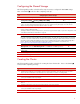
The following table provides a checklist of the required software versions and, if applicable, any items
to execute before beginning the installation. Place a checkmark (3) in the box after completing each
step.
3
Software and Hardware Requirements
Before installing your HP ProLiant F200 for MSA1500 cluster solution, it is very important to refer to the HP Cluster
Configuration Support website for details on components that make up a valid cluster configuration. There is a support
matrix for each HP Cluster that details components that represent quality tested and supported HP Cluster
configurations.
Using the link below, select the appropriate operating system and storage platform and then refer to the row of
deliverables that are relevant to the configuration you require.
The HP Cluster Configuration Support website can be found at
http:/h18022.www1.hp.com/solutions/enterprise/highavailability/answercenter/configuration-all.html
SmartStart CD
Two supported ProLiant Servers, supported fibre channel adapters, two or more supported network adapters, two
supported fibre channel switches or hubs, and one or more MSA1500(s).
Review and understand any Read This First and Getting Started cards that were shipped with the product.
Microsoft Windows 2000 Advanced Server software and documentation
Microsoft Windows 2000 Advanced Server Service Pack
HP StorageWorks MSA1500 Support Software CD
Array Configuration Utility (ACU), which is located on the HP MSA1500 Support Software CD
HP Insight Manager (optional)
MSA1500 controller firmware version 6.0 or later for Active/Active controller support.
FCA firmware and boot bios
Fibre Channel switch firmware
HP MPIO Full Featured DSM for Windows for MSA Disk Arrays
Sufficient software rights to install the operating system and software applications on each node.
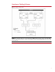
Ensure all hardware is installed and properly cabled as shown in figure 1 - hardware cabling scheme on page 3.