HP Pavilion ze5600 Notebook PC HP Pavilion ze5500 Notebook PC HP Pavilion ze5400 Notebook PC HP Pavilion ze5300 Notebook PC HP Pavilion ze5200 Notebook PC HP Pavilion ze4700 Notebook PC HP Pavilion ze4600 Notebook PC HP Pavilion ze4500 Notebook PC HP Pavilion ze4400 Notebook PC HP Pavilion ze4300 Notebook PC HP Pavilion ze4200 Notebook PC HP Pavilion ze4100 Notebook PC HP Compaq nx9010 Notebook PC HP Compaq nx9008 Notebook PC HP Compaq nx9005 Notebook PC HP Compaq nx9000 Notebook PC Compaq Evo Notebook N105
© Copyright 2003, 2004 Hewlett-Packard Development Company, L.P. Microsoft and Windows are U.S. registered trademarks of Microsoft Corporation. Intel, Celeron, and Pentium are trademarks or registered trademarks of Intel Corporation or its subsidiaries in the United States and other countries. The information contained herein is subject to change without notice. The only warranties for HP products and services are set forth in the express warranty statements accompanying such products and services.
Contents Introduction..................................................................................................................... vii Product Information...................................................................................................... 1-1 Features ................................................................................................................................................ 1-8 Operation............................................................................
Figures Figure 1-1. Front View................................................................................................................................ 1-8 Figure 1-2. Back View ................................................................................................................................ 1-9 Figure 1-3. Bottom View........................................................................................................................... 1-10 Figure 1-4. Front View....................
Figure 2-36. Disconnecting the Motherboard Cables ............................................................................... 2-54 Figure 2-37. Removing the Motherboard.................................................................................................. 2-56 Figure 2-38. Example of Serial Number Label ......................................................................................... 2-59 Figure 2-39. Replacing the Antennas..............................................................
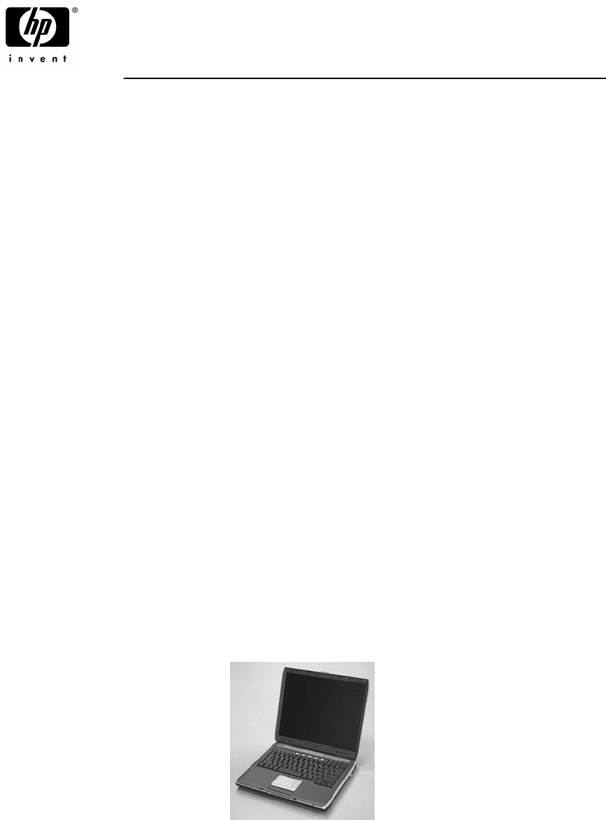
Introduction This manual provides reference information for servicing the HP Pavilion ze5600, ze5500, ze5400, ze5300, ze5200, ze4700, ze4600, ze4500, ze4400, ze4300, ze4200, and ze4100 Notebook PCs, HP Compaq nx9010, nx9008, nx9005, and nx9000 Notebook PCs, Compaq Evo Notebook 1050v and 1010v Series, and Compaq Presario 2500, 2100, and 1100 Series Mobile PCs. These notebook models use technology code KE.
1 Product Information The following list of HP and Compaq notebook products is current at the time of publication but is subject to change. Table 1-1. Product Comparisons HP Pavilion ze5600 Processor Intel® Celeron® (2.6-, 2.8-GHz) Mobile Intel Pentium® 4 (2.4-, 2.66-, 2.8-, and 3.06-GHz) Memory Up to 1 GB (1024 MB) SDRAM using 512-MB modules. At least 256 MB SDRAM preinstalled. Display 15.
HP Pavilion ze5400 and ze5300 Processor Mobile Intel Pentium 4 (2.4-, 2.66-, 2.8-, and 3.06-GHz) Memory Up to 1 GB (1024 MB) SDRAM using 512-MB modules. At least 256 MB SDRAM preinstalled. Display 15.0-inch XGA (1024 × 768) or SXGA+ (1400 × 1050) or 14.
HP Pavilion ze4600 Processor AMD Athlon (1.47-, 1.53-, 1.67-, 1.8-, 2.2-, and 2.08-GHz) Memory Up to 1 GB (1024 MB) SDRAM using 512-MB modules. At least 128 MB SDRAM preinstalled. Display 15.0-inch XGA (1024 × 768) or SXGA+ (1400 × 1050) or 14.
HP Pavilion ze4300 Processor Mobile Intel Pentium 4-M (1.8-, 2.0-, 2.2-, and 2.4-GHz) Intel Celeron (1.8-, 2.0-, and 2.2-GHz) AMD Athlon (1.47-, 1.53-, 1.67-, 1.8-, 1.87-, and 2.0-GHz) Memory Up to 1 GB (1024 MB) SDRAM using 512-MB modules. At least 128 MB SDRAM preinstalled. Display 15.0-inch XGA (1024 × 768) or SXGA+ (1400 × 1050) or 14.
HP Compaq nx9010 Processor Mobile Intel Pentium 4 (2.4-, 2.53-, 2.66-, and 3.06-GHz) Intel Celeron (2.0- and 2.6-GHz) Memory Up to 1 GB (1024 MB) SDRAM using 512-MB modules. At least 256 MB SDRAM preinstalled. Display 15.
HP Compaq nx9000 Processor AMD Athlon (1.8- or 2.0-GHz) Memory Up to 1 GB (1024 MB) SDRAM using 512-MB modules. At least 256 MB SDRAM preinstalled. Display 15.
Compaq Presario 2500 Processor Mobile Intel Pentium 4 (2.0-, 2.3-, 2.4-, 2.53-, 2.66-, 2.8-, and 3.06-GHz) Intel Celeron (2.6- and 2.8-GHz) Memory Up to 1 GB (1024 MB) SDRAM using 512-MB modules. At least 256 MB SDRAM preinstalled. Display 15.0-inch XGA (1024 × 768) or SXGA+ (1400 × 1050) or 14.
Features The following illustrations show the notebook’s main external features. For an exploded view of the notebook, see page 4-2. Figure 1-1. Front View HP Pavilion ze4x00, HP Compaq nx9005 and nx9000, Compaq Evo Notebook N1050v and N1010v, and Compaq Presario 2100 and 1100 1. Notebook open/close latch 7. Microphone option (not available) 2. One-touch buttons 8. Infrared port* 3. Keyboard status lights 9. Wireless on-off button and indicator light* 4.
Figure 1-2. Back View HP Pavilion ze4x00 HP Compaq nx9005 and nx9000 NOTE: Compaq Evo Notebook N1050v, N1010v, and Compaq Presario 2100 and 1100 are very similar, except for logo. 13. AC adapter jack 21. Modem port* 14. Two universal Serial Bus (USB) ports 22. PCMCIA card and CardBus slot and button 15. LAN port* 23. IEEE 1394 port* 16. S-Video port* 24. Audio jacks (left to right), external microphone and audio out (headphones) 17.
Figure 1-3. Bottom View HP Pavilion ze4x00, HP Compaq nx9005 and nx9000, Compaq Evo Notebook N1050v and N1010v, and Compaq Presario 2100 and 1100 28. Hard disk drive 31. Reset button 29. Battery latch 32. Port replicator connect* 30. SDRAM door 33.
Figure 1-4. Front View HP Pavilion ze5x00, HP Compaq nx9010 and nx9008, and Compaq Presario 2500 1. Notebook open/close latch 8. Wireless on-off button and indicator light* 2. One-touch buttons 9. Audio mute button and audio mute light* 3. Keyboard status lights 10. Battery 4. Power button, turns the notebook on and off 11. Volume controls* 5. Touch pad, scroll pad, Select buttons, plus on-off button 12. Audio jacks (left to right): external microphone and audio out (headphones) 6.
Figure 1-5. Back View HP Pavilion 5x00, HP Compaq nx9010, and nx9008 and Compaq Presario 2500 15. AC adapter jack 21. S-Video port* 16. Two universal Serial Bus (USB) ports 22. Kensington lock cable slot (security connector) 17. LAN port* 23. Modem port* 18. External keyboard/mouse port 24. IEEE 1394 port* 19. Parallel port (LPT1), use this port for a parallel printer or other parallel device 25. PCMCIA card and CardBus slot and button 20.
Figure 1-6. Bottom View HP Pavilion 5x00, HP Compaq nx9010,and nx9008, and Compaq Presario 2500 27. Hard disk drive 31. Port replicator connect* 28. Battery latch 32. Reset button 29. Mini PCI door (no user parts inside) * on certain models 30.
Operation This section gives an overview of the notebook’s operation. Turning the Notebook On and Off You can start and stop your notebook using its power button. However, at certain times you might want to use other methods to start or stop the notebook—depending on power considerations, types of active connections, and start-up time. NOTE: This manual describes the notebook in its original factory configuration, with all settings at their default values. Table 1-2.
Checking the Status of the Notebook The main status lights on the front of the notebook report power status, battery status, and hard disk activity. Table 1-3. Main Status Lights (front of notebook) Meaning Power status On: notebook is on (even if the display is off). Blinking: notebook is in Standby mode. Off: notebook is off or in Hibernation mode. Hard disk drive activity On: notebook is accessing the hard disk drive. Battery status Green: The AC adapter is connected and the battery is fully charged.
Using Fn Hot Keys The combination of the Fn key plus another key creates a hot key—a shortcut key sequence—for various system controls. To use a hot key, press and hold Fn, press the appropriate second key, then release both keys. Table 1-5. Fn Hot Keys Hot Key Effect Fn+F1 Decreases the display brightness Fn+F2 Increases the display brightness Fn+F5 Toggles among the built-in display, an external display, and simultaneous display on both. Fn+F8 Toggles the built-in keypad on and off.
Resetting the Notebook Occasionally, Windows or the notebook might stop responding, so that you cannot turn the notebook off. If this happens, try the following in the order listed. Press the power button to restart. • If possible, shut down Windows: press ctrl+alt+del, and then select Shut Down > Restart. If the system will not allow a software shutdown, press and hold down the power button until the display shuts down (about 4 seconds) and then release the power button.
Specifications The following tables list the specifications for the notebook and its accessories and are subject to change. For the latest versions, see the HP Notebook Web site http://www.hp.com/notebooks. Table 1-6. Specifications Physical Attributes Size (14-inch display): 328 × 272 × 33 mm (12.9 × 10.7 × 1.3 in) Size (15-inch display): 328 × 272 × 35 mm (12.9 × 10.7 × 1.4 in) Weight: 2.9 kg (6.5 lb) minimum, depending on configuration Processor and Bus Architecture HP Pavilion ze5600: 2.4-, 2.66-, 2.
Processor and Bus Architecture (continued) Compaq Evo Notebook N1050v: 1.8-GHz Mobile Intel Pentium 4 Processor-M with Intel Speed Step technology, 512-KBL2 cache, and 1.2- to 1.3-V core low-power processor with 400-MHz processor system bus -or1.6-GHz Intel Celeron processor with 256-KB L2 cache and 1.45-V core low-power processor with 133-MHz processor system bus Compaq Evo Notebook N1010v: 1.6-GHz Intel Celeron processor with 256-KB L2 cache and 1.
Mass Storage 20- to 60-GB removable hard drive with Ultra-DMA 100 interface 1.
Table 1-7. Accessories Accessory Description Pavilion ze5x00, nx9010, nx9008, and Presario 2500 Pavilion ze4x00, nx9005, and Evo N1050v Pavilion ze4200, nx9000, and Presario 2100 Evo N1010v and Presario 1100 Pavilion ze4100 Memory F4694-60901 317434-001 128MB DDR266B • • • • • F4695-60901 317435-001 256MB DDR266B • • • • • F4696-60901 317436-001 512MB DDR266B • • • 0950-4193 319412-001 HDD-20 GB 9.5mm, Hitachi ATA100 • • • 0950-4318 • Hard Drives • • HDD-20 GB 9.
Accessory Description Pavilion ze5x00, nx9010, nx9008, and Presario 2500 Pavilion ze4x00, nx9005, and Evo N1050v Pavilion ze4200, nx9000, and Presario 2100 Evo N1010v and Presario 1100 Pavilion ze4100 317444-291 317444-AD1 SPS-CORD-AC PWR 2 WIRE-KOR • 8120-8373 317444-AA1 Cord, Pwr, People’s Republic of China AB2 (2w) • 317444-101 SPS-CORD-AC PWR 2 WIRE-SWE • 317444-111 SPS-CORD-AC PWR 2 WIRE-SWI • 317444-AB1 SPS-CORD-AC PWR 2 WIRE-TAI • 8120-8699 317444-031 Cord, Pwr, UK (EPSR) for H
Internal Design The motherboard PCA is the central component of the notebook’s design. It plays a role in virtually all system functions. The CPU module and most other subsystems connect to the motherboard. The following figure shows the connections among the notebook’s replaceable electronic modules. Table 1-8 on page 1-25 lists the roles that these modules play in the notebook’s functional subsystems. Figure 1-8.
Table 1-8. Functional Structure Description Bootup CPU module Motherboard Hard disk drive Floppy drive Main processor (MMO) Primary system circuitry, system BIOS First source of disk-based startup code Second source of disk-based startup cod.
2 Removal and Replacement This chapter tells you how to remove and replace the notebook’s components and assemblies. The items marked by • in the following table are user-replaceable. Table 2-1.
Table 2-2. Required Equipment • 0 and 1 Phillips screwdrivers, preferably magnetized • Small flat-blade screwdriver • 5mm nut driver Table 2-3. Recommended Screw Torque Values 2-2 Screw Thread Size Torque (cm-kgf) Torque (in-lbf) M2 2,0–2,5 1.7–2.2 M2.5 (hinges) 3,5–4,0 3.0–3.4 M2.5 (other) 2,5–3,0 2.2–2.6 M3 2,5–3,0 2.2–2.6 Standoff, hex 2,5–3,0 2.2–2.
Disassembly Flowchart The following diagram shows the general “path” you will use when disassembling the notebook to access any particular component. Figure 2-1.
Removing the Battery (User-Replaceable) Required Equipment None Removal Procedure Slide the battery’s release latch, and then pull the battery out of its compartment. Figure 2-2.
Removing an SDRAM Module (User-Replaceable) The notebook has no system memory built into its motherboard, but has 2 slots for SDRAM modules. One slot contains an SDRAM module that was factory installed. NOTE: HP Pavilion ze5300, ze5200, ze4300, ze4200, and ze4100, HP Compaq nx9010, nx9005 and nx9000, Compaq Evo Notebook N1050v and N1010v, and Compaq Presario 2500, 2100, and 1100 notebooks use only DDR266 SDRAM modules. Using the wrong type of module prevents the notebook from booting.
NOTE: The SDRAM door on HP Pavilion ze5x00, HP Compaq nx9010 and nx9008, and Compaq Presario 2500 models is located in the rear left corner of the notebook bottom, as indicated in Figure 2-4. The procedure for removing the SDRAM door and modules is the same for all notebook models. Figure 2-4.
Removing the Wireless LAN Mini PCI Card (User-Replaceable) Certain notebooks include a wireless LAN Mini PCI card under the Mini PCI door on the bottom of the notebook. CAUTION: Handle the Mini PCI card only by its edges and provide proper grounding, or you might damage the card through electrostatic discharge. Required Equipment 0 Phillips screwdriver Removal Procedure 1. Unplug the AC adapter, if present, and then remove the battery. 2.
NOTE: The Mini PCI Card door on HP Pavilion ze5x00, HP Compaq nx9010 and HP nx9008, and Compaq Presario 2500 models is located in the front center area of the notebook bottom, as indicated in Figure 2-6. The procedure for removing the Mini PCI door and card is the same for all notebook models. Figure 2-6.
Removing the Hard Disk Drive (User-Replaceable) Required Equipment 1 Phillips screwdriver Removal Procedure NOTE: If you are installing a new hard disk drive, load the factory software and operating system on the drive as described in “Recovering the Factory Software”, as shown on the next page. 1. Unplug the AC adapter, if present, and then remove the battery. 2. On the bottom of the notebook, remove the hard disk drive rubber screw plugs and M2.5×6.0mm screws.
4. Remove the four M3.0×4.0mm screws from the hard disk drive and hard disk drive tray, and then lift the drive out of the tray. 5. Remove the connector bar from the hard disk drive. See note below NOTE: Connector bar not used on HP Pavilion ze5x00 series Figure 2-8.
Recovering the Factory Software The following procedure describes how to recover the notebook’s original operating system and drivers. This process can take up to 15 minutes to complete. (For more information about recovering the factory software installation, see the readme.txt file in the root directory of the Recovery CDs.) CAUTION: Do not interrupt the following process or unplug the AC adapter until the process completes. 1. Connect the AC adapter to the notebook. 2.
Replacing Small Parts The user can replace the following small parts. Table 2-4. Replacing Small Parts Part Replacement Procedure Rubber screw plugs, display (on display bezel) Insert a small flat-blade screwdriver under the rubber screw plug and pry it loose. To replace, firmly press the adhesive side of the screw plug into the recess. Door, Mini PCI On the bottom of the notebook, loosen the screws that secure the Mini PCI door to the bottom case, and then remove the door.
Removing the Keyboard Cover Required Equipment • 1 Phillips screwdriver • Small flat-blade screwdriver Removal Procedure 1. Unplug the AC adapter, if present, and then remove the battery. 2. Remove the two M2.5×4.0mm hinge cover screws that secure the keyboard cover to the rear of the notebook. 3. Carefully insert a flat-blade screwdriver blade under the keyboard cover near the right end, then near the center, then near the left end, and then gently lift up the center of the cover.
4. If necessary, while holding the center of the cover, carefully insert the flat-blade screwdriver under the right side of the display assembly hinge, gently pry up, and then lift the cover out. This procedure might need to be repeated on the left side of display assembly hinge to completely remove the cover. Figure 2-9.
Removing the Speaker Assembly (User-Replaceable) NOTE: The following speaker assembly removal procedures apply only to HP Pavilion 4x00, HP Compaq nx9005 and nx9000, Compaq Evo Notebook N1050v and N1010v, and Compaq Presario 2100 and 1100 Series notebooks. The HP Pavilion ze5x00, HP Compaq nx9010 and nx9008, and Compaq Presario 2500 Series notebook speakers are integrated into the top case.
Removing the Keyboard Required Equipment 1 Phillips screwdriver Removal Procedure 1. Unplug the AC adapter, if present, and then remove the battery. 2. Remove the keyboard cover (page 2-13). 3. Remove the four M2.5×4.0mm screws that secure the keyboard to the top case. 4. Lift up on the keyboard at the switchboard PCA end, and then pull it toward the display assembly to release the tabs from the top case. 5. Turn the keyboard over, and then disconnect the motherboard cable. 6. Remove the keyboard.
Figure 2-12.
Removing the Switchboard PCA NOTE: This section applies only to HP Pavilion 4x00, HP Compaq nx9005 and nx9000, Compaq Evo Notebook N1050v and N1010v, and Compaq Presario 2100 and 1100 models. Required Equipment 1 Phillips screwdriver Removal Procedure 1. Unplug the AC adapter, if present, and then remove the battery. 2. Remove the keyboard cover (page 2-13). 3. Disconnect both the 2-wire and 4-wire cables that connect the switchboard PCA to the top case and speaker assembly, respectively. 4. Remove the M2.
NOTE: This section applies only to HP Pavilion 5x00, HP Compaq nx9010 and nx9008, and Compaq Presario 2500 models. Required Equipment 1 Phillips screwdriver Removal Procedure 1. Unplug the AC adapter, if present, and then remove the battery. 2. Remove the keyboard cover (page 2-13). 3. Disconnect the 2-wire cable that connects the switchboard PCA to the display lid switch. 4. Remove the two M2.5×4.0mm screws that secure the switchboard PCA to the top case. 5.
Removing the CD/DVD Drive NOTE: This section applies only to HP Pavilion 4x00, HP Compaq nx9005 and nx9000, Compaq Evo Notebook N1050v and N1010v, and Compaq Presario 2100 and 1100 models. Required Equipment 1 Phillips screwdriver Removal Procedure 1. Unplug the AC adapter, if present, and then remove the battery. 2. Remove these additional assemblies: • Keyboard cover (page 2-13) • Keyboard (page 2-16) 3. Remove the 2 screws that secure the CD/DVD drive to the top case and motherboard.
NOTE: This section applies only to HP Pavilion 5x00, HP Compaq nx9010 and nx9008, and Compaq Presario 2500 models. Required Equipment 1 Phillips screwdriver Removal Procedure 1. Unplug the AC adapter, if present, and then remove the battery. 2. Remove these additional assemblies: • Keyboard cover (page 2-13) • Keyboard (page 2-16) 3. Remove the two M2.5×6.0mm screws that secure the CD/DVD drive to the top case and motherboard. 4.
Removing the Display Assembly (Service Partners Only) Required Equipment 1 Phillips screwdriver Removal Procedure 1. Unplug the AC adapter, if present, and then remove the battery. 2. Remove the keyboard cover (page 2-13). 3. Remove the two M2.5×6.0mm retaining screws from the notebook rear panel. 4. Remove the M2.5×4.0mm screws from the left and right antenna PCAs. Relocate the antenna PCAs away from the display assembly hinges. 5. Disconnect the display assembly cable from the motherboard. 6.
. Figure 2-17. Removing the Display Assembly Reassembly Notes NOTE: After replacing the display assembly or motherboard, you must use the Service Utilities floppy disk to reprogram the EEPROM on the motherboard for the new display. 1. Download the notebook series service package from the Partnership Web site (see page vii), and then create a Service Utilities floppy disk as described in the package’s Readme file. 2. Plug in an AC adapter. 3. Insert the Service Utilities floppy disk in the floppy drive.
Removing the Top Case (Service Partners Only) NOTE: This section applies only to HP Pavilion 4x00, HP Compaq nx9005 and nx9000, Compaq Evo Notebook N1050v and N1010v, and Compaq Presario 2100 and 1100 models. Required Equipment 1 Phillips screwdriver Removal Procedure 1. Unplug the AC adapter, if present, and remove the battery. 2.
Figure 2-18.
NOTE: This section applies only to HP Pavilion 5x00, HP Compaq nx9010 and HP nx9008, and Compaq Presario 2500 models. Required Equipment 1 Phillips screwdriver Removal Procedure 1. Unplug the AC adapter, if present, and then remove the battery. 2. Remove these additional assemblies: • Hard disk drive (page 2-9) • Keyboard cover (page 2-13) • Speaker assembly (page 2-15) • Keyboard (page 2-16) • Switchboard PCA (page 2-19) • CD/DVD drive (page 2-20) • Display assembly (page 2-23) 3.
Figure 2-19. Removing the Top Case Screws HP Pavilion 5x00, HP Compaq nx9010 and nx9008, and Compaq Presario 2500 Models 5. Turn the notebook top side up with the rear panel facing forward. 6. Remove the two M2.5×7.0mm screws from the rear of the bottom case. Figure 2-20.
7. Position the notebook so the front faces forward. 8. Disconnect the floppy drive flex cable from the low insertion force (LIF) connector to which it is connected. 9. Release the ZIF connector to which the TouchPad cable is connected, and then disconnect the TouchPad cable from the system board. 10. Remove the following 4 screws: • One M2.5×7.0mm screw next to the TouchPad cable • Two M2.5×6.0mm screws in the center of the top case • One M2.5×4.
Removing the Floppy Drive (Service Partners Only) NOTE: This section applies only to HP Pavilion ze4x00, HP Compaq nx9005 and nx9000, Compaq Evo Notebook N1050v and N1010v, and Compaq Presario 2100 and 1100 models. Required Equipment 1 Phillips screwdriver Removal Procedure 1. Unplug the AC adapter, if present, and remove the battery. 2.
Figure 2-22. Removing the Floppy Drive HP Pavilion 4x00, HP Compaq nx9005 and nx9000, Compaq Evo Notebook N1050v and N1010v, and Compaq Presario 2100 and 1100 Models Reassembly Notes CAUTION: Do not excessively bend or fold the floppy drive cable. Excessive flexing can damage the floppy drive cable connections. • Connect the floppy drive cable to the motherboard prior to replacing the floppy drive and hard disk drive guide.
NOTE: This section applies only to HP Pavilion 5x00, HP Compaq nx9010 and nx9008, and Compaq Presario 2500 models. Required Equipment • 1 Phillips screwdriver Removal Procedure 1. Unplug the AC adapter, if present, and then remove the battery. 2. Remove these additional assemblies: • Hard disk drive (page 2-9) • Keyboard cover (page 2-13) • Keyboard (page 2-16) • Switchboard PCA (page 2-19) • Display assembly (page 2-23) • Top case (page 2-26) 3.
Figure 2-23. Removing the Floppy Drive HP Pavilion 5x00, HP Compaq nx9010 and nx9008, and Compaq Presario 2500 Models Reassembly Notes CAUTION: Do not excessively bend or fold the floppy drive cable. Excessive flexing can damage the floppy drive cable connections.
Removing the Infrared (I/R) PCA (Service Partners Only) Required Equipment 1 Phillips screwdriver Removal Procedure 1. Unplug the AC adapter, if present, and then remove the battery. 2.
3. Disconnect the I/R PCA cable from the motherboard. 4. Remove the two M2.5×4.0mm screws that secure the I/R PCA to the bottom case. 5. Remove the I/R PCA. Figure 2-24. Removing the I/R PCA Reassembly Note CAUTION: Use care when handling the I/R PCA cable. Damaging the cable can degrade notebook performance. Make sure you route the I/R PCA cable between the left screw hole and the bottom case.
Removing the Audio PCA (Service Partners Only) NOTE: The following audio PCA removal instructions apply only to HP Pavilion 5300 and 5200, HP Compaq nx9010, and Compaq Presario 2500 models. Required Equipment 1 Phillips screwdriver Removal Procedure 1. Unplug the AC adapter, if present, and then remove the battery. 2.
7. Remove the M2.0×3.0mm flathead screw that secures the audio PCA to the bottom case. 8. Remove the audio PCA. Figure 2-25. Removing the Audio PCA Reassembly Note CAUTION: Use care when handling the audio PCA cable. Damaging the cable can degrade notebook performance. Make sure you route the audio PCA cable into the clip on the bottom case.
Removing the Heat Sink (with Fan) (Service Partners Only) NOTE: This section applies only to HP Pavilion 4x00, HP Compaq nx9005 and nx9000, Compaq Evo Notebook N1050v and N1010v, and Compaq Presario 2100 and 1100 models. Required Equipment 0 Phillips screwdriver Removal Procedure 1. Unplug the AC adapter, if present, and then remove the battery. 2.
3. Remove the three M2.5×4.0mm retaining screws. 4. Lift up on the heat sink (with fan), and then disconnect the fan cable from the motherboard. Figure 2-26. Removing the Heat Sink (with Fan) HP Pavilion 4x00, HP Compaq nx9005 and nx9000, Compaq Evo Notebook N1050v and N1010v, and Compaq Presario 2100 and 1100 Models CAUTION: Do not spin the fan blades with your finger or you could damage the fan’s bearings.
NOTE: This section applies only to HP Pavilion 5x00, HP Compaq nx9010 and HP nx9008, and Compaq Presario 2500 models. Required Equipment 0 Phillips screwdriver Removal Procedure 1. Unplug the AC adapter, if present, and then remove the battery. 2.
3. Disconnect the 2 fan cables from the motherboard. 4. Remove the 4 retaining M2.0×5.0mm screws in the “1,” “2,” “3,” “4” sequence stamped on the heat sink. 5. Lift up on the heat sink (with fan). Figure 2-27. Removing the Heat Sink (with Fan) HP Pavilion 5x00, HP Compaq nx9010 and nx9008, and Compaq Presario 2500 Models CAUTION: Do not spin the fan blades with your finger or you could damage the fan’s bearings.
Removing the CPU Module (Authorized Service Providers Only) Required Equipment Small flat-blade (3mm) screwdriver NOTE: This section applies only to HP Pavilion 4x00, HP Compaq nx9005 and nx9000, Compaq Evo Notebook N1050v and N1010v, and Compaq Presario 2100 and 1100 models. Removal Procedure 1. Unplug the AC adapter, if present, and then remove the battery. 2.
3. Depending on model configuration, an Intel or an AMD CPU module mey be installed. For models using an AMD CPU, proceed to step 4. On models using an Intel CPU, proceed with the following substeps: a. Turn the lock screw one-half turn counterclockwise (you should here a light snap) to release the CPU module ( see Figure 2-28). b. Carefully lift the CPU module off the socket on the motherboard. Figure 2-28.
4. On models using an AMD CPU, proceed with the following substeps: a. Place a flat-blade screwdriver (with a 3mm blade) into the slot at the angle shown in Figure 2-29 and move the screwdriver in the directon shown by the arrow until a Select is felt or heard. Figure 2-29 AMD CPU Module Release HP Pavilion 4x00, HP Compaq nx9005 and nx9000, Compaq Evo Notebook N1050v and N1010v, and Compaq Presario 2100 and 1100 Models b.
c. To install an AMD CPU module, insert the module into the socket on the motherboard (the CPU module is keyed for installation and can be inserted only in one way). d. Place the flat-blade screwdriver into the position shown in Figure 2-31 and move as indicated by the arrow in the illustration below to secure the CPU module into the socket. Figure 2-31.
NOTE: This section applies only to HP Pavilion 5x00, HP Compaq nx9010 and nx9008, and Compaq Presario 2500 models. Removal Procedure 1. Unplug the AC adapter, if present, and then remove the battery. 2.
3. Slide the front tip of the locking arm slightly to the right, and then swing it up and back. 4. Carefully lift the CPU module off of its socket on the motherboard. Figure 2-32. Removing the CPU Module HP Pavilion ze5x00, HP nx9010 and HPnx9008, and Compaq Presario 2500 Models Reassembly Notes CAUTION: Each time you install a new CPU module, you must also replace the heat sink’s thermal pad to maintain optimum heat transfer.
Removing the RJ11/1394 Connector Module (Service Partners Only) NOTE: The following RJ11/1394 connector module removal instructions apply only to HP Pavilion 5x00, HP Compaq nx9010 and nx9008, and Compaq Presario 2500 models. Required Equipment Small flat-blade screwdriver Removal Procedure 1. Unplug the AC adapter, if present, and then remove the battery. 2.
6. Disconnect the 1394 cable from the motherboard. 7. Remove the M2.5×6.0mm screw that secures the RJ11/1394 connector module to the bottom case. 8. Remove the RJ11/1394 connector module. Figure 2-33.
Removing the Motherboard (Service Partners Only) NOTE: This section applies only to HP Pavilion 4x00, HP Compaq nx9005 and nx9000, Compaq Evo Notebook N1050v and N1010v, and Compaq Presario 2100 and 1100 models. Required Equipment 1 Phillips screwdriver Removal Procedure NOTE: Before Replacing the Motherboard If possible, record the computer’s electronic serial number before you replace the motherboard.
CAUTION: Wireless Models Be careful when removing and attaching antenna cables. Damage to cables or connectors can degrade performance. 3. Wireless models only: Remove the Mini PCI door and unplug the 2 antenna cables from the Mini PCI card. Do not remove the Mini PCI card at this time. 4. Remove the four M2.5×4.0mm screws (indicated by the small arrows in Figure 2-34) that secure the motherboard to the bottom case. 5.
NOTE: This section applies only to HP Pavilion 5x00, HP Compaq nx9010, HP nx9008, and Compaq Presario 2500 models. Required Equipment 1 Phillips screwdriver Removal Procedure NOTE: Before Replacing the Motherboard If possible, record the computer’s electronic serial number before you replace the motherboard. You will then store the electronic serial number in the EEPROM on the new motherboard using the Service Utility floppy disk. 1.
CAUTION: Wireless Models Be careful when removing and attaching antenna cables. Damage to cables or connectors can degrade performance. 3. Wireless models only: Remove the Mini PCI door, and then unplug the 2 antenna cables from the Mini PCI card. Do not remove the Mini PCI card at this time. 4. Remove the two M2.0×4.0mm screws that secure the PCMCIA assembly to the bottom case. 5. Remove the 4 screws that secure the hard disk drive guide to the bottom case.
7. Disconnect the modem board cable from the motherboard. 8. Disconnect the 1394 board cable from the motherboard. 9. Disconnect the fan cable from the motherboard and remove the fan. 10. Disconnect the audio board cable from the motherboard. Figure 2-36. Disconnecting the Motherboard Cables 11. Remove the four M5.0×10mm standoffs from the notebook rear panel (2 on each side of the parallel and external monitor connectors). 12. Remove the three M2.5×6.
15. Remove the CD/DVD drive front alignment rail. 16. Remove the two M2.5×6.0mm countersink screws (one on the front edge of the motherboard, the other on the left edge of the motherboard) that secure the motherboard to the bottom case. 17. Remove the two M2.0×5.0mm screws that secure the motherboard to the bottom case on the back edge of the motherboard. 18. Remove the antenna cable from the metal holder on the motherboard. 19. Carefully lift the motherboard out of the bottom case. 20.
Reassembly Notes NOTE: After replacing the display assembly or motherboard, you must use the Service Utilities floppy disk to reprogram the EEPROM on the motherboard for the new display. 1. Download the notebook Series service package from the Partnership Web site (see page vii), and create a Service Utilities floppy disk as described in the package’s Readme file. 2. Plug in an AC adapter. 3. Insert the Service Utilities floppy disk in the floppy drive.
Reassembly Procedure CAUTION: Be extremely careful when replacing the motherboard. The motherboard has EMI springs attached to it that can bend very easily. Bending any EMI spring could cause a motherboard short. NOTE: Reprogramming the BIOS IC A new BIOS IC contains only enough basic programming to enable the notebook to boot. After installing a new motherboard, you must reprogram the BIOS IC, preferably with the latest BIOS—(see page 2-60.) 1.
Replacing Components on a Bottom Case Reassembly Procedure 1. Transfer the plastic wireless panel, and if present, the docking port cover from the old bottom case to the new bottom case. 2. Install a new Microsoft Product ID label. 3. Transfer the old serial number label, and install a new overlay, or create a new serial number label using the steps below. 4. Follow the “Reassembly Notes” on page 2-52.
Replacing the Left and Right Antennas If you need to remove or replace an antenna, see the figure below. CAUTION: Handle the connector ends of the antennas carefully. Failure to do so could degrade notebook performance. Handle the antenna routing metal tabs in the bottom case carefully. These tabs can be easily broken. 1. Carefully remove both antennas from the old bottom case. 2. Route both antenna cables through the new bottom case as shown below.
Repairing the BIOS IC (Service Partners Only) The notebook’s BIOS IC cannot be replaced separately. If it is defective, you must replace the motherboard. In some cases, however, you might be able to reprogram a malfunctioning BIOS IC using either e-DiagTools for Windows, a BIOS floppy disk, or a Crisis Recovery floppy disk. If the notebook will boot sufficiently, use e-DiagTools for Windows or a BIOS floppy disk to reprogram the BIOS IC.
Using a BIOS Floppy Disk If you do not have a BIOS floppy disk, download the package from the Partnership Web site (see page vii) under Product Support Information in the Service and Support Library. Follow the instructions for creating the BIOS floppy disk. CAUTION: Make sure to use the correct BIOS floppy disk for the notebook model you are repairing. The program does not verify the notebook model, so you could accidentally install the wrong BIOS. 1. Insert the BIOS floppy disk in the floppy disk drive.
Removing Other Components (Service Partners Only) Required Equipment • 0 and 1 Phillips screwdrivers • Small flat-blade screwdriver Removal Procedure 1. Unplug the AC adapter, if present, and then remove the battery. 2. Remove the assemblies, and then follow the additional steps listed in the table below. Table 2-5.
Component Removal Procedure Additional Steps Guide, HDD Keyboard cover(page 2-13) When replacing the HDD guide, make sure you only replace the 2 right screws. Do not replace the 2 left screws.
3 Troubleshooting and Diagnostics This chapter includes troubleshooting and diagnostic information for testing the functionality of the notebook, and for identifying faulty components: • ASP support information • Troubleshooting information Checking for customer abuse (page 3-4) Troubleshooting the problem (page 3-5) Verifying the repair (page 3-6) Suggestions for troubleshooting (page 3-7) • Diagnostic tools e-Diagtools diagnostic program (page 3-18) Power-on self-test (page 3-20) Sycard PCCtest 450/4
Support by Authorized Service Providers In the U.S., support of notebook computers by Authorized Service Providers (ASPs) is a purchasable option. Standard predefined models and standard special models do not include ASP support. The sales force has the option of creating models with ASP support using the specials process. The serial number label on the bottom of the notebook indicates the ASP support status for that model. See the following table. Table 3-1.
Troubleshooting The suggestions in this section can help isolate and repair the cause of a problem. To ensure quality repair, follow the basic troubleshooting steps shown below. Check the customer’s description of the problem and any supporting information. Check for customer abuse. Try to duplicate the customer’s problem. Troubleshoot the problem using: - Diagnostic tools. - Troubleshooting suggestions. Verify the repair by testing the functionality of the complete unit. Figure 3-1.
Checking for Customer Abuse Some notebooks might appear to have been damaged by customer abuse. Use these guidelines to help determine if this is the case: • If the shipping box is seriously damaged, customer abuse cannot be declared. • If the damage could have a cause other than customer abuse, customer abuse cannot be declared.
Troubleshooting the Problem Record pertinent information about the notebook: • Model and serial number • Operating system and version • Software version (stored in hidden fileC:\version.inf) • BIOS version • Accessories and peripherals used Analyze the problem: • Observe Symptoms. Using the customer’s information, try to duplicate the problem. Determine how the problem differs from proper behavior. Also, note the functions that do work properly. • Separate Problems.
Verifying the Repair Before returning the repaired notebook to the customer, verify the repair by running the following tests: • e-Diagtools Basic Diagnostic Test. Run the basic test of the e-Diagtools diagnostic program (page 3-18). –and– • Function Tests. Run tests that check the repaired function, such as those in e-Diagtools (page 3-18). –and– • 3-6 Failed Tests. Run any other tests that failed during troubleshooting.
Suggestions for Troubleshooting Table 3-2.
If you cannot isolate the cause of a problem using the above diagnostic tools, use the suggestions in the following table to help find the problem. Table 3-3. Troubleshooting Suggestions Symptom Call Center: Suggestions Repair Center: Likely Causes Repair Center: Comments To help determine likely causes of a problem, determine which replaceable modules are involved in the system function and what roles they play. See the figure on page 1-24 and the table on page 1-25.
Symptom Call Center: Suggestions Does not boot on battery, but boots on AC Make sure battery is properly installed and fully charged. Check battery level on battery LEDs. Repair Center: Likely Causes Repair Center: Comments Battery or contacts Motherboard Check battery contacts. If available, try another battery. Does not boot from floppy drive Does not boot from CD in CD/DVD drive Make sure floppy disk is bootable. Floppy disk or floppy drive Use BIOS Setup to check default boot order.
Repair Center: Likely Causes Symptom Call Center: Suggestions No power Make sure charged battery is installed or AC adapter connected. AC adapter Try another battery or AC adapter if available. Motherboard Make sure AC adapter has correct power rating. Battery or contacts Battery does not charge Make sure AC adapter is connected properly and battery installed properly.
Repair Center: Likely Causes Repair Center: Comments Make sure notebook is turned on and warmed up. Display cable connection Check cable connections. Check power supply. SDRAM modules Make sure SDRAM modules are installed properly. CPU module Replace SDRAM modules. Adjust display brightness. Display assembly Press Fn+F5 several times.
Symptom Call Center: Suggestions Erratic display Repair Center: Likely Causes Repair Center: Comments Display cable connection Check display cable connection. Switchboard PCA Display assembly Motherboard Bright or missing pixels or lines. See quality statement on page 5-3. Display cable connection Check display cable connection. Display assembly See quality statement on page 53. Punctured display Declared to be caused by customer abuse. Vertical crack near center of display.
Symptom Call Center: Suggestions Files corrupted Run virus scan program. Repair Center: Likely Causes Repair Center: Comments Check hard disk using Tools tab in disk’s Properties sheet. Test hard disk drive with e-Diagtools diagnostics. Back up files if possible, then use Recovery CDs to reformat hard disk and reinstall factory software. Disk capacity less than normal Check hard disk using Tools tab in disk’s Properties sheet.
Symptom Call Center: Suggestions Region Code error DVDs contain embedded regional codes that prevent them from playing outside region in which they are sold. This error occurs when trying to play DVD intended for different region. Repair Center: Likely Causes Repair Center: Comments HP warranty does not cover expense of correcting this situation. NOTE: Most DVD drives allow region code to be changed only a limited number of times (usually no more than 4).
Symptom Call Center: Suggestions Repair Center: Likely Causes Repair Center: Comments Touch pad General problems Reset notebook (see page 1-17). Top case Motherboard Check settings in Control Panel. Make sure touch pad is enabled in Mouse Properties. By default, touch pad is disabled if external PS/2 mouse is connected, Use BIOS Setup to check settings. Avoid touching touch pad while booting or resuming.
Symptom Call Center: Suggestions Repair Center: Likely Causes Check connections. Motherboard Repair Center: Comments Serial/Parallel/USB General problems Restart notebook. Use troubleshooters in Windows Help. Check settings in Control Panel. Check port settings in Device Manager. Test ports with e-Diagtools diagnostics. For USB: contact device vendor and HP Notebook Web site (see page vii) for latest USB drivers. For USB: if the device is powered by the USB port, try the other port.
Symptom Call Center: Suggestions Repair Center: Likely Causes Check cables and connections. Motherboard Repair Center: Comments LAN/network General problems Try connecting notebook to another network station (if applicable). If green light next to LAN port does not light, LAN cable may not be connected to network or network may be down. Use networking troubleshooter in Windows Help. Check settings in Control Panel.
Symptom Call Center: Suggestions Repair Center: Likely Causes Repair Center: Comments Mini PCI card Make sure all cables are properly connected to Mini PCI card and motherboard. Check for damaged coaxial cables or connectors. Wireless General problems Check TCP/IP setup in Control Panel. Check SSID, channel, and encryption settings.
Symptom Repair Center: Likely Causes Repair Center: Comments Plug in AC adapter for 24 hours to charge CMOS battery. CMOS battery Charge CMOS battery. Always set notebook on a flat surface, so air can flow freely around and underneath it. Heat sink Call Center: Suggestions Miscellaneous Clock loses time Notebook gets abnormally hot Motherboard Check thermal contact between CPU and heat sink. Replace thermal pad if needed. Make sure air vents are not blocked.
Diagnostic Tools This section describes the following diagnostic tools you can use for troubleshooting and repairing the notebook: • Notebook e-Diagtools diagnostic program (below) • Power-on self-test (page 3-20) • Sycard PCCtest 450 PC card (page 3-26) • Windows Management Instrumentation (page 3-27) • BIOS Setup utility (page 3-27) e-Diagtools Diagnostic Program The hardware diagnostic programs provide two levels of testing: • User-level testing using a basic hardware test.
11. Exit. Press F3 and then any key to exit and reboot. 12. Optional: open the Support Ticket. In Windows, select Start > All Programs (or Programs) > Hewlett-Packard > Notebook > HP e-Diagtools > e-Diagtools for Windows. 13. Select View to display the Support Ticket. 14. To add information about your problem, select Comments, type the information, and then select OK. To save or print the Support Ticket, select Save As or Print. To e-mail the Support Ticket to your support agent, select e-Mail.
Power-On Self-Test NOTE: If Quiet Boot is enabled in BIOS Setup (the default setting), press esc during boot to see POST messages. When the notebook boots, its system BIOS runs a series of initialization routines and diagnostic tests called POST (Power-On Self-Test). The BIOS will not boot the notebook’s operating system if the system memory, CPU, DMA, or interrupt controller fails the POST diagnostic tests.
Beep Codes POST Description 1-2-1-2 Load alternate registers with initial POST values 1-2-1-3 Restore CPU control word during warm boot 1-2-1-4 Initialize PCI Bus Mastering devices 1-2-2-1 Initialize keyboard controller 1-2-2-3 1-2-2-4 BIOS ROM checksum Initialize cache before memory Auto size 1-2-3-1 8254 timer initialization 1-2-3-3 8237 DMA controller initialization 1-2-4-1 Reset Programmable Interrupt Controller 1-3-1-1 Test DRAM refresh 1-3-1-3 Test 8742 Keyboard Controller (on mot
Beep Codes 2-1-4-4 Initialize MultiBoot 2-2-1-1 Display CPU type and speed 2-2-1-2 Initialize EISA board 2-2-1-3 Test keyboard 2-2-2-1 Set key Select if enabled 2-2-2-2 Enable USB devices 2-2-3-1 2-2-3-2 3-24 POST Description Test for unexpected interrupts Initialize POST display service 2-2-3-3 Display prompt "Press F2 to enter SETUP" 2-2-3-4 Disable CPU cache 2-2-4-1 Test RAM between 512 and 640 KB 2-3-1-1 Test extended memory 2-3-1-3 Test extended memory address lines 2-3-2-1 J
Beep Codes POST Description 3-1-3-2 Enable Non-Maskable Interrupts (NMIs) 3-1-3-3 Initialize Extended BIOS Data Area 3-1-3-4 Test and initialize PS/2 mouse 3-1-4-1 Initialize floppy controller 3-1-4-4 Determine number of ATA drives (optional) 3-2-1-1 Initialize hard-disk controllers 3-2-1-2 Initialize local-bus hard-disk controllers 3-2-1-3 Jump to UserPatch2 3-2-1-4 Build MPTABLE for multi-processor boards 3-2-2-2 Install CD-ROM for boot 3-2-2-3 Clear huge ES segment register 3-2-2-
Beep Codes 3-26 POST Description 3-4-4-4 Check virus and backup reminders 4-1-1-1 Try to boot with INT 19 4-1-1-2 Initialize POST Error Manager (PEM) 4-1-1-3 Initialize error logging 4-1-1-4 Initialize error display function 4-1-2-1 Initialize system error handler 4-1-2-2 PnPnd dual CMOS (optional) 4-1-2-3 Initialize note dock (optional) 4-1-2-4 Initialize note dock late 4-1-3-1 Force check (optional) 4-1-3-2 Extended checksum (optional) 4-1-3-3 Redirect Int 15h to enable remote ke
Beep Codes POST Description 4-4-2-1 Output one beep 4-4-2-2 Clear Huge Segment 4-4-2-3 Boot to Mini DOS 4-4-2-4 Boot to Full DOS 1 long, 2 short Service Manual Improper video configuration (reprogram EEPROM) or external ROM checksum failure Troubleshooting and Diagnostics 3-27
The following table lists POST messages and explanations for reported problems If the system fails after you make changes in BIOS Setup, reset the notebook, enter BIOS Setup, and install the defaults or correct the error.
Message Description 02D0 System cache error— Cache disabled RAM cache failed and BIOS disabled the cache May require replacing the motherboard A disabled cache slows system performance considerably 02F0: CPU ID CPU socket number for Multi-Processor error 02F4: EISA CMOS Not Writeable ServerBIOS2 test error: Cannot write to EISA CMOS 02F5: DMA Test Failed ServerBIOS2 test error: Cannot write to extended Direct Memory Access (DMA) registers 02F6: Software NMI Failed ServerBIOS2 test error: Cannot g
Message Description Press to resume, to Setup, for previous Displayed after any recoverable error message Press to start the boot process or to enter BIOS Setup and change the settings Press to display the previous screen (usually an initialization error of an Option ROM, such as an add-on card) Write down and follow the information shown on the screen Press to enter Setup Optional message displayed during POST PS/2 Mouse PS/2 mouse identified System BIOS shadowed
Sycard PCCtest 450/460 PC Card (Optional) The PCCtest 450 and 460 cards (version 105) from Sycard Technology are the only recommended diagnostic tools that test the functionality of the PCMCIA slots using a PCMCIA card Each is a Type II PC card that works with test software to exercise PCMCIA functions (For details, see the Sycard Technology Web site http://wwwsycardcom/). The PCCtest product contains these components: • PCCtest 450 or 460 (revision 1.
Windows Management Instrumentation (WMI) The Windows Management Instrumentation is basically sets of rules for accessing information about a notebook WMI allows an application to determine, for example, the operating system being used, which hardware and software components are in the notebook, and possibly whether any of the components need replacing A local or remote application can use the WMI interface to check which hardware and software components are installed on your notebook, and might be able to t
BIOS Setup Utility The BIOS Setup utility provides access to the notebook’s basic configuration settings It is independent of the operating system Running the BIOS Setup Utility 1. Close all applications, then restart the notebook: select Start > Turn Off Computer > Restart. (If necessary, you can press ctrl+alt+del to restart.) 2. When the HP logo appears, press F2 to enter the BIOS Setup utility. 3. The pointing devices are not active in BIOS Setup, so you will need to use the keyboard to navigate.
Table 3-7 BIOS Setup Menus and Parameters All notebook models: Introduced with BIOS version KE.01.
System Devices Menu Description Default Video Display Device Sets whether the built-in display automatically switches to an external display, if one is detected Disables the internal pointing devices when an external pointing device is connected Enables BIOS support for USB mouse, keyboard, and floppy drive during startup Lets the notebook be turned on via the LAN port If this option is enabled, the notebook uses increased power while it is shut down Auto External Pointing Devices Legacy USB Support
4 Replaceable Parts This chapter contains an exploded view of the notebook and the following lists of parts: • Notebook replaceable parts (page 4-3) • Accessory replacement parts (page 4-11) • Part number reference (page 4-12) Service Manual Replaceable Parts 4-1
Figure 4-1 Exploded View HP Pavilion 4x00, HP Compaq nx9005 and nx9000, and Compaq Presario 2100 4-2 Replaceable Parts Service Manual
Figure 4-2 Exploded View HP Pavilion 5x00, HP Compaq nx9010 and nx9008, and Compaq Presario 2500 Service Manual Replaceable Parts 4-3
Table 4-1 Replaceable Parts Description Part Number Exchange Part Number Pavilion ze5x00, nx9010, nx9008, and Presario 2500 Pavilion ze4x00, Evo N1050v, Pavilion ze4200, nx9000, and Presario 2100 and Presario 2100 • • Evo N1010, and Presario 1100 Pavilion ze4100 F5771J F5761H • User Repl 1 Cover, Keyboard– 1F Pavilion F576160904 319428-001 1 Cover, Keyboard– 1F Compaq F577160904 319430-001 1 SPS-COVER, KEYBOARD W/SPEAKERS CPQ 319479-001 • No 1 SPS-COVER, KEYBOARD W/SPEAKERS PAV
Description Part Number Exchange Part Number Pavilion ze5x00, nx9010, nx9008, and Presario 2500 Pavilion ze4x00, Evo N1050v, Pavilion ze4200, nx9000, and Presario 2100 and Presario 2100 Evo N1010, and Presario 1100 Pavilion ze4100 F5771J F5761H • User Repl 2 SPS-DSPLY PANEL 150-inch SXGA PRES 319488-001 2 SPS-DSPLY PANEL 150-inch SXGA CPQ 319441-001 • • No 2 SPS-DSPLY PANEL 150-inch XGA CPQ 319440-001 • • No 2 SPS-DSPLY PANEL 141-inch XGA CPQ 319439-001 • • No 3 Speaker a
Description Part Number Exchange Part Number Pavilion ze5x00, nx9010, nx9008, and Presario 2500 Pavilion ze4x00, Evo N1050v, Pavilion ze4200, nx9000, and Presario 2100 and Presario 2100 Evo N1010, and Presario 1100 Pavilion ze4100 F5771J F5761H User Repl 5 SPSKEYBOARD-GRK F464060916 317443-151 • • No 5 SPSKEYBOARD-HE F464060917 317443-BB1 • • No 5 SPSKEYBOARD-HUN F464060918 317443-211 • • No 5 SPSKEYBOARD-ICL 317443-DD1 • • No 5 SPSKEYBOARD-INTL F464060920 317443-002
Description Part Number Exchange Part Number Pavilion ze5x00, nx9010, nx9008, and Presario 2500 Pavilion ze4x00, Evo N1050v, Pavilion ze4200, nx9000, and Presario 2100 and Presario 2100 Evo N1010, and Presario 1100 Pavilion ze4100 F5771J F5761H User Repl 5 SPSKEYBOARD-THAI 317443-281 • • No 5 SPSKEYBOARD-TK F464060930 317443-141 • • No 5 Keybd, UK F464060931 317443-031 • • • 5 Keybd, US ENGLISH F464060932 317443-001 • • • 6 Case, top–1F (Pavilion) F576160906 6 Case,
Description Part Number Exchange Part Number Pavilion ze5x00, nx9010, nx9008, and Presario 2500 Pavilion ze4x00, Evo N1050v, Pavilion ze4200, nx9000, and Presario 2100 and Presario 2100 • • Evo N1010, and Presario 1100 Pavilion ze4100 F5771J F5761H • • User Repl 8 Heat sink–1F w/fan F464060947 319456-001 8 SPS-HEATSINK 3F W/2 FANS 319492-001 • No 8 HEATSINK /FAN AMD, 53W 361380-001 • No Thermal pad, set F464060984 317438-001 • 9 Kit, door–PCMCIA 1F Upper Door w/ Spring Lowe
Description Part Number Exchange Part Number Pavilion ze5x00, nx9010, nx9008, and Presario 2500 Pavilion ze4x00, Evo N1050v, Pavilion ze4200, nx9000, and Presario 2100 and Presario 2100 Evo N1010, and Presario 1100 Pavilion ze4100 F5771J F5761H User Repl 10 CPU, Cel-M 17 GHz Northwood uFCPGA 1822-0990 319464-001 F576569204 • • 10 CPU, Cel-M 16 GHz Northwood uFCPGA 1822-0989 319463-001 F576569203 • • 10 CPU, Cel-M 15 GHz Northwood UfcPGA 1822-1024 F576569202 10 SPS-PROC ATH XP20
Description Part Number Exchange Part Number Pavilion ze4x00, Pavilion ze5x00, nx9010, nx9008, and Presario 2500 Evo N1050v, Pavilion ze4200, nx9000, and Presario 2100 and Presario 2100 Evo N1010, and Presario 1100 Pavilion ze4100 F5771J F5761H User Repl 12 CD-ROM Assy–24x F464060934 319420-001 • • • • • No 12 DVD Assy–8x F464060936 319421-001 • • • • • No 12 CD-RW/DVD Combo Assy F464060937 319422-001 • • • • • No 12 SPS-DVD+RW 319423-001 • • No 12 SPS-DRV CD-
Description Part Number Exchange Part Number Pavilion ze5x00, nx9010, nx9008, and Presario 2500 Pavilion ze4x00, Evo N1050v, and Presario 2100 and Presario 2100 • • • • Yes • • Yes Yes 17 Tray, HDD–1F F464060903 319417-001 18 SPS-DRV HD 60 G (4200rpm) 319415-001 18 SPS-DRV HD 60 G (5400 rpm) 319416-001 18 SPS-DRV HD 80 G (4200 rpm) 320692-001 • • • 18 HDD-40 GB 95mm, IBM ATA100 FDB 0950-4320 319414-001 • • • 18 HDD-40 GB 95mm, Toshiba ATA100 0950-4288 18 HDD-30 GB 95mm
Description Part Number Exchange Part Number Pavilion ze5x00, nx9010, nx9008, and Presario 2500 Pavilion ze4x00, Evo N1050v, Pavilion ze4200, nx9000, and Presario 2100 and Presario 2100 • • Evo N1010, and Presario 1100 Pavilion ze4100 F5771J F5761H • • User Repl 19 Kit, rubber foot and screw plug F464060969 317437-001 20 SPS PANEL IR 3F W/IR & BUTTON 319502-001 • No 20 SPS PANEL IR 3F W/IR & W/O BTN 319503-001 • No 20 Panel, IR–1F w/o IR & w/ button F464060948 317439-001 •
Table 4-2 Accessory Replaceable Parts Pavilion ze5x00, nx9010, nx9008, Description Part Number and Presario 2500 Pavilion ze4x00, nx9005, Evo N1050v, Pavilion ze4200, nx9000, and Presario 2100 and Presario 2100 Evo N1010v, Presario 1100 Pavilion ze4100 F5771J H5761H User Repl 128MB DDR266B F4694-60901 317434-001 • • • • Yes 256MB DDR266B F4695-60901 317435-001 • • • • Yes 512MB DDR266B F4696-60901 317436-001 • • • Yes AC-Adapter-Ultraslim Delta 75W s/PFC F4600-60901 • •
Table 4-3 Part Number Reference Pavilion ze5x00, nx9010, nx9008 and Presario 2500 Pavilion ze4x00, nx9005, Evo N1050v and Presario 2100 Pavilion ze4200, nx9000 and Presario 2100 Evo N1010 v and Presari o 1100 F5771J Pavilion ze4100 H5761H User Repl • • • • • Yes Part Description Exchange Part Number 0950-4162 F2072-69115 HDD-300GB 9.5mm, IBM (diablo) ATA100 0950-4168 F3257-69106 HDD-30GB 9.5mm, Hitachi ATA100 • • Yes 0950-4176 F3257-69103 HDD-30GB 9.
Part Description Exchange Part Number Description Pavilion ze5x00, nx9010, nx9008 and Presario 2500 Pavilion ze4x00, nx9005, Evo N1050v and Presario 2100 Pavilion ze4200, nx9000 and Presario 2100 Evo N1010 v and Presari o 1100 F5771J Pavilion ze4100 H5761H User Repl 317433-001 SPS-ENCLOSURE BASE DF • • No 317434-001 128MB DDR266B • • Yes 317435-001 256MB DDR266B • • 317436-001 512MB DDR266B • • 317437-001 Kit, rubber foot and screw plug • • 317438-001 Thermal pad, set • 317
Part Description Exchange Part Number Description Pavilion ze5x00, nx9010, nx9008 and Presario 2500 Pavilion ze4x00, nx9005, Evo N1050v and Presario 2100 Pavilion ze4200, nx9000 and Presario 2100 Evo N1010 v and Presari o 1100 F5771J Pavilion ze4100 H5761H User Repl 317443-251 SPS-KEYBOARD-RU • • No 317443-281 SPS-KEYBOARD-THAI • • No 317443-291 Keybd, JAPANESE • • 317443-AA1 SPS-KEYBOARD-PRC • • No 317443-AB1 SPS-KEYBOARD-TAI • • No 317443-AD1 SPS-KEYBOARD-KO • • No 31
Part Description Exchange Part Number Description Pavilion ze5x00, nx9010, nx9008 and Presario 2500 Pavilion ze4x00, nx9005, Evo N1050v and Presario 2100 Pavilion ze4200, nx9000 and Presario 2100 Evo N1010 v and Presari o 1100 F5771J Pavilion ze4100 H5761H User Repl • No 317445-001 PCA, switchboard w/cable 1F Pavilion • • 317446-001 SPS-BD switch w/ cable 1F CPQ • • No 317447-001 SPS-LABEL NAME SET • • Yes 317448-001 Port Replicator Assy • • 317473-001 Kit, rubber foot and scre
Part Description Exchange Part Number Description Pavilion ze5x00, nx9010, nx9008 and Presario 2500 Pavilion ze4x00, nx9005, Evo N1050v and Presario 2100 Pavilion ze4200, nx9000 and Presario 2100 Evo N1010 v and Presari o 1100 F5771J Pavilion ze4100 H5761H User Repl 19436-001 Display 14.1-inch XGA– Pavilion KE • • • No 319437-001 Display 15.0-inch XGA– Pavilion KE • • • No 319438-001 Display 15.0-inch SXGA+– Pavilion KE • • • No 319439-001 SPS-DSPLY PANEL 15.
Part Description Exchange Part Number Description Pavilion ze5x00, nx9010, nx9008 and Presario 2500 Pavilion ze4x00, nx9005, Evo N1050v and Presario 2100 Pavilion ze4200, nx9000 and Presario 2100 Evo N1010 v and Presari o 1100 F5771J Pavilion ze4100 H5761H User Repl 319470-001 Base Enclosure DF • No 319477-001 SPS-CASE TOP 3F CPQ FF • No 319478-001 SPS-CASE, TOP 3F PAV FF • No 319479-001 SPS-COVER, KEYBOARD W/SPEAKERS CPQ • No 319480-001 SPS-PROC DT P4 1.
Part Description Exchange Part Number Description Pavilion ze5x00, nx9010, nx9008 and Presario 2500 Pavilion ze4x00, nx9005, Evo N1050v and Presario 2100 Pavilion ze4200, nx9000 and Presario 2100 Evo N1010 v and Presari o 1100 F5771J Pavilion ze4100 H5761H User Repl 319848-001 SPS-PROC ATH XP1800+ 1.53-GHz 45W • No 319849-001 SPS-PROC ATH XP2000+ 1.67-GHz 45W • No 319850-001 SPS-PROC ATH XP1700+ 1.
Part Description Exchange Part Number Description Pavilion ze5x00, nx9010, nx9008 and Presario 2500 Pavilion ze4x00, nx9005, Evo N1050v and Presario 2100 Pavilion ze4200, nx9000 and Presario 2100 Evo N1010 v and Presari o 1100 F5771J Pavilion ze4100 H5761H User Repl F4640-60928 SPS-KEYBOARD-SWI • • No F4640-60929 SPS-KEYBOARD-PRC • • No F4640-60930 SPS-KEYBOARD-TK • • No F4640-60931 Keybd, UK • • • F4640-60932 Keybd, US ENGLISH • • • F4640-60933 PCA, switchboard w/cable– 1
Part Description Exchange Part Number Description Thermal pad, set F4640-60984 Pavilion ze5x00, nx9010, nx9008 and Presario 2500 Pavilion ze4x00, nx9005, Evo N1050v and Presario 2100 Pavilion ze4200, nx9000 and Presario 2100 Evo N1010 v and Presari o 1100 F5771J Pavilion ze4100 H5761H User Repl • • • • No • No F4640-60986 F4640-69086 Case, bottom assy–w/1394 W2K/XPPro • F4640-60987 F4640-69087 Case, bottom assy–w/1394 XPHome • F4641-60905 Cover, docking port HP/Compaq • • Yes F
5 Reference Information This chapter includes the following reference information: • Password removal policy • Display quality statement Service Manual Reference Information 5-1
Password Removal Policy If the user forgets the system password, the user calls Technical Support to determine the proper removal procedure The user must provide proof of ownership and the notebook must be operated during the procedure. The password removal procedure is protected as HP Company Private information There are a restricted number of locations that can perform password removal It might not be disclosed or distributed outside those locations.
Hewlett-Packard Display Quality Statement TFT display manufacturing is a highly precise but imperfect technology, and manufacturers cannot produce large displays that are cosmetically perfect. Most, if not all, TFT displays exhibit some level of cosmetic imperfection. These cosmetic imperfections might be visible to the customer under varying display conditions, and can appear as bright, dim, or dark spots.
Table 5-1 LCD Guidelines Type of Imperfection Imperfections Not Allowed Electrical Imperfections: • 7 or more single bright dots Bright dots (a) • 7 or more single dark dots • 9 or more total (bright and dark combined) defective dots • Any occurrence of multiple defective dots within 15 mm • Any polarizer bubble, discoloration, or dent that is visible from at least 36 cm (14 in) Dark dots (a) Mechanical Imperfections: Discoloration Polarizer bubbles, dents (b) Definitions of imperfections: a
Service Notes and Obsolete Part Service notes containing important repair information for these products will be issued as needed. These notes are available online at the Partnership Web site (see page vii).