
Maintenance and Service Guide
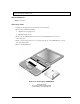
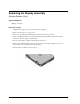
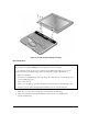
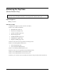
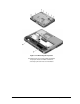
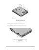
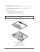
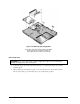
Table Of Contents
- Contents
- Introduction
- Product Information
- Removal and Replacement
- Disassembly Flowchart
- Removing the Battery
- Removing an SDRAM Module
- Removing the Wireless LAN Mini PCI Card
- Removing the Hard Disk Drive
- Recovering the Factory Software
- Replacing Small Parts
- Removing the Keyboard Cover
- Removing the Speaker Assembly
- Removing the Keyboard
- Removing the Switchboard PCA
- Removing the CD/DVD Drive
- Removing the Display Assembly
- Removing the Top Case
- Removing the Floppy Drive
- Removing the Infrared (I/R) PCA
- Removing the Audio PCA
- Removing the Heat Sink (with Fan)
- Removing the CPU Module
- Removing the RJ11/1394 Connector Module
- Removing the Motherboard
- Replacing Components on a Bottom Case
- Repairing the BIOS IC
- Removing Other Components
- Troubleshooting and Diagnostics
- Replaceable Parts
- Reference Information
2-22 Removal and Replacement Service Manual
Removing the Display Assembly
(Service Partners Only)
Required Equipment
1 Phillips screwdriver
Removal Procedure
1. Unplug the AC adapter, if present, and then remove the battery.
2. Remove the keyboard cover (page 2-13).
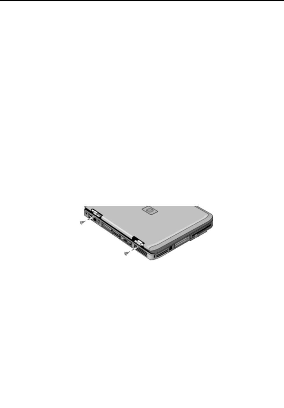
3. Remove the two M2.5×6.0mm retaining screws from the notebook rear panel.
4. Remove the M2.5×4.0mm screws from the left and right antenna PCAs. Relocate the antenna
PCAs away from the display assembly hinges.
5. Disconnect the display assembly cable from the motherboard.
6. Remove the six M2.5×6.0mm retaining screws that secure the display assembly to the top case.
(Note that there is a grounding strap at the left hinge.)
7. Lift the display assembly off of the notebook.