
Maintenance and Service Guide
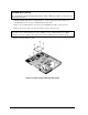
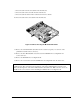
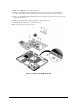
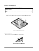
Table Of Contents
- Contents
- Introduction
- Product Information
- Removal and Replacement
- Disassembly Flowchart
- Removing the Battery
- Removing an SDRAM Module
- Removing the Wireless LAN Mini PCI Card
- Removing the Hard Disk Drive
- Recovering the Factory Software
- Replacing Small Parts
- Removing the Keyboard Cover
- Removing the Speaker Assembly
- Removing the Keyboard
- Removing the Switchboard PCA
- Removing the CD/DVD Drive
- Removing the Display Assembly
- Removing the Top Case
- Removing the Floppy Drive
- Removing the Infrared (I/R) PCA
- Removing the Audio PCA
- Removing the Heat Sink (with Fan)
- Removing the CPU Module
- Removing the RJ11/1394 Connector Module
- Removing the Motherboard
- Replacing Components on a Bottom Case
- Repairing the BIOS IC
- Removing Other Components
- Troubleshooting and Diagnostics
- Replaceable Parts
- Reference Information
2-52 Removal and Replacement Service Manual
CAUTION: Wireless Models
Be careful when removing and attaching antenna cables. Damage to cables or connectors can
degrade performance.
3. Wireless models only: Remove the Mini PCI door, and then unplug the 2 antenna cables from
the Mini PCI card. Do not remove the Mini PCI card at this time.
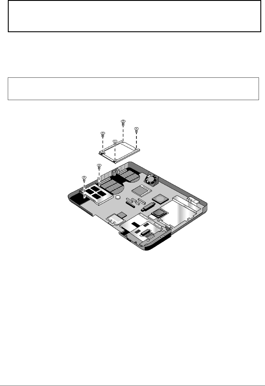
4. Remove the two M2.0×4.0mm screws that secure the PCMCIA assembly to the bottom case.
5. Remove the 4 screws that secure the hard disk drive guide to the bottom case.
NOTE: The 4 screws that secure the hard disk drive guide are 2 different sizes. The screw in the
upper left corner is a M2.5×6.0mm screw. The remaining 3 screws are M2.0×4.0mm screws. Make
sure these screws are installed in the correct locations when reinstalling the hard disk drive guide.
6. Remove the hard disk drive guide.
Figure 2-35. Removing the Hard Disk Drive Guide