
Maintenance and Service Guide
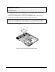
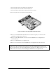
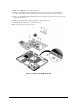
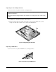
Table Of Contents
- Contents
- Introduction
- Product Information
- Removal and Replacement
- Disassembly Flowchart
- Removing the Battery
- Removing an SDRAM Module
- Removing the Wireless LAN Mini PCI Card
- Removing the Hard Disk Drive
- Recovering the Factory Software
- Replacing Small Parts
- Removing the Keyboard Cover
- Removing the Speaker Assembly
- Removing the Keyboard
- Removing the Switchboard PCA
- Removing the CD/DVD Drive
- Removing the Display Assembly
- Removing the Top Case
- Removing the Floppy Drive
- Removing the Infrared (I/R) PCA
- Removing the Audio PCA
- Removing the Heat Sink (with Fan)
- Removing the CPU Module
- Removing the RJ11/1394 Connector Module
- Removing the Motherboard
- Replacing Components on a Bottom Case
- Repairing the BIOS IC
- Removing Other Components
- Troubleshooting and Diagnostics
- Replaceable Parts
- Reference Information
2-54 Removal and Replacement Service Manual
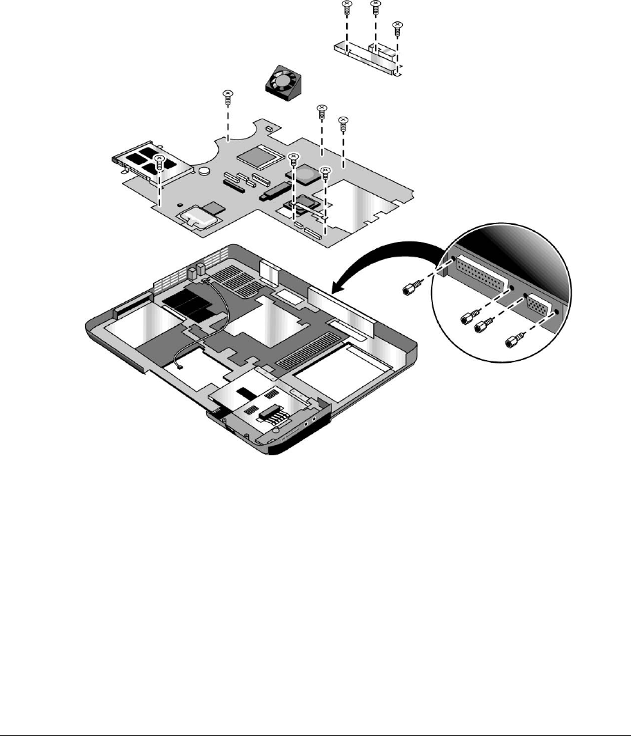
15. Remove the CD/DVD drive front alignment rail.
16. Remove the two M2.5×6.0mm countersink screws (one on the front edge of the motherboard,
the other on the left edge of the motherboard) that secure the motherboard to the bottom case.
17. Remove the two M2.0×5.0mm screws that secure the motherboard to the bottom case on the back
edge of the motherboard.
18. Remove the antenna cable from the metal holder on the motherboard.
19. Carefully lift the motherboard out of the bottom case.
20. If present, remove the modem port cover.
Figure 2-37. Removing the Motherboard