
Maintenance and Service Guide
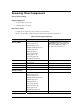
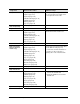

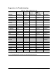
Table Of Contents
- Contents
- Introduction
- Product Information
- Removal and Replacement
- Disassembly Flowchart
- Removing the Battery
- Removing an SDRAM Module
- Removing the Wireless LAN Mini PCI Card
- Removing the Hard Disk Drive
- Recovering the Factory Software
- Replacing Small Parts
- Removing the Keyboard Cover
- Removing the Speaker Assembly
- Removing the Keyboard
- Removing the Switchboard PCA
- Removing the CD/DVD Drive
- Removing the Display Assembly
- Removing the Top Case
- Removing the Floppy Drive
- Removing the Infrared (I/R) PCA
- Removing the Audio PCA
- Removing the Heat Sink (with Fan)
- Removing the CPU Module
- Removing the RJ11/1394 Connector Module
- Removing the Motherboard
- Replacing Components on a Bottom Case
- Repairing the BIOS IC
- Removing Other Components
- Troubleshooting and Diagnostics
- Replaceable Parts
- Reference Information
2-62 Removal and Replacement Service Manual
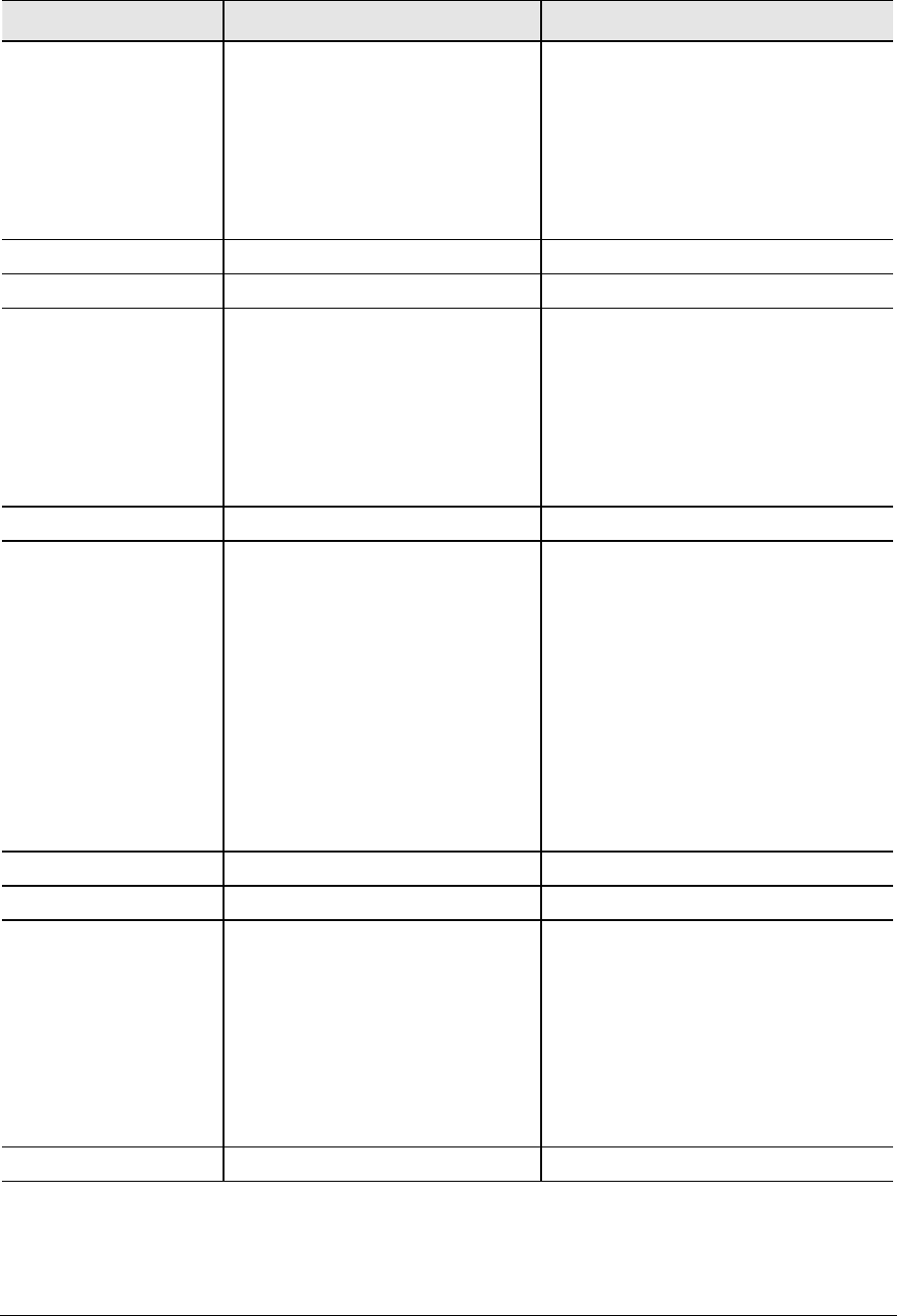
Component Removal Procedure Additional Steps
Guide, HDD
Keyboard cover(page 2-13)
Speaker (page 2-15)
Keyboard (page 2-16)
Switchboard PCA(page 2-19)
CD/DVD (page 2-20
Display (page 2-23)
Top case (page 2-26
When replacing the HDD guide, make
sure you only replace the 2 right screws.
Do not replace the 2 left screws.
Heat sink (with fan)
See page page 2-32
Keyboard
See page 2-3
Panel, wireless
Keyboard cover(page 2-13)
Speaker (page 2-15)
Keyboard (page 2-16)
Switchboard PCA(page 2-19)
CD/DVD (page 2-20
Display (page 2-23)
Top case (page 2-26)
Press the tabs on both sides of the panel,
and then lift it from the bottom case.
PCA, I/R
See page 2-36
PCA, left and right
antennas (wireless
models only)
Keyboard cover(page 2-13)
Speaker (page 2-15)
Keyboard (page 2-16)
Switchboard PCA(page 2-19)
CD/DVD (page 2-20
Display (page 2-23)
Top case (page 2-26)
Floppy (page 2-32)
Heat sink (page 2-40)
Motherboard (page 2-50)
Bottom case (page 2-59)
Disconnect the front antenna PCA cables
from the Mini PCI card (page 2-7).
Be careful not to bend the metal tabs on
the bottom case when removing or
replacing either of the 2 antenna PCAs.
PCA, motherboard
See page 2-50
PCA, switchboard
See page 2-3
Socket, PCMCIA
Keyboard cover(page 2-13)
Keyboard (page 2-16)
CD/DVD (page 2-20)
Display (page 2-23)
Top case (page 2-26)
Floppy (page 2-32)
Heat sink (page 2-40)
Motherboard (page 2-50)
1. Remove the 2 screws attaching the
socket to the motherboard.
2. Unplug the PCMCIA socket from the
motherboard.
Speaker assembly
See page 2-3.