Maintenance & Service Guide HP Compaq Pro 4300 All-in-One Business PC
© Copyright 2012 Hewlett-Packard Development Company, L.P. The information contained herein is subject to change without notice. Microsoft and Windows are trademarks of Microsoft Corporation in the U.S. and other countries. The only warranties for HP products and services are set forth in the express warranty statements accompanying such products and services. Nothing herein should be construed as constituting an additional warranty.
About This Book WARNING! Text set off in this manner indicates that failure to follow directions could result in bodily harm or loss of life. CAUTION: Text set off in this manner indicates that failure to follow directions could result in damage to equipment or loss of information. NOTE: Text set off in this manner provides important supplemental information.
Table of contents 1 Product Features ............................................................................................................................................ 1 Overview .............................................................................................................................................. 1 Front Components ................................................................................................................................ 3 Side Components .............
SATA Data Cable .............................................................................................................. 24 SMART ATA Drives ............................................................................................................................ 25 Hard Drive Capacities ........................................................................................................................ 25 5 Routine Care and Disassembly Preparation ................................................
Fan ..................................................................................................................................................... 63 Converter Board ................................................................................................................................. 65 Sidekey Board .................................................................................................................................... 67 System Board Shield ....................................
9 Backup and Recovery ................................................................................................................................ 135 Restoring and recovering in Windows 7 ........................................................................................... 135 System Restore ............................................................................................................... 135 System Recovery ............................................................................
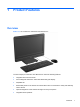
1 Product Features Overview Figure 1-1 HP Compaq Pro 4300 All-in-One Business PC The HP Compaq Pro 4300 All-in-One Business PC offers the following features: ● Integrated All-in-One form factor ● 20-inch diagonal widescreen 1600 x 900 WLED anti-glare display ● Adjustable tilt ● Removable panels on the back of the chassis allow users or technicians to easily and efficiently service the PC ● Optional integrated 1.
2 ● Choice of wired or wireless keyboard and mouse ● Windows® 7 or Windows 8 operating system ● 6-in-1 media card reader ● 6 USB 2.0 ports ● Tray-load HP SuperMulti DVD+/-RW SATA Drive ● Up to 1 TB hard drive ● 2nd and 3rd generation Intel® Core™ processors ● Intel H61 Express Chipset ● Integrated Intel HD Graphics ● Integrated Gigabit network connection (Realtek RTL 8111 F Gigabit Ethernet) ● Up to 16 GB of DDR3 SDRAM memory ● Optional wireless LAN (802.11 a/g/n, 802.
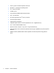
Front Components Figure 1-2 Front Components Table 1-1 Front Components Component Component 1 Webcam 4 Power button and LED 2 Single microphone 5 High-performance stereo speakers 3 20-inch diagonal 16:9 widescreen LED-backlit LCD display Front Components 3
Side Components Figure 1-3 Side Components Table 1-2 Side Components 4 Component Component 1 HP USB Media Card Reader 6 Optical disc drive activity LED 2 (2) USB 2.
Rear Components Figure 1-4 Rear Components Table 1-3 Rear Components Component Component 1 Drive access panel 7 Security lock slot 2 Center access panel 8 Power connector with LED indicator 3 Memory access panel 9 RJ-45 Gigabit Ethernet port 4 Optical disc drive location 10 Stereo audio line out 5 Hard drive location 11 (4) USB 2.
Adjusting Tilt Tilt the computer forward up to -5 degrees or backward up to +25 degrees to set it to a comfortable eye level.
2 Activating and Customizing the Software NOTE: This chapter provides information for both Windows 7 and Windows 8. Activating and customizing the software in Windows 7 If your computer was not shipped with a Windows® operating system, some portions of this documentation do not apply. Additional information is available in online help after you activate the operating system. CAUTION: Do not add optional hardware or third-party devices to the computer until the operating system is successfully activated.
Downloading Windows 7 updates Microsoft may release updates to the operating system. To help keep the computer running optimally, HP recommends checking for the latest updates during the initial installation and periodically throughout the life of the computer. 1. To set up your Internet connection, click Start > Internet Explorer and follow the instructions on the screen. 2. After an Internet connection has been established, click the Start > All Programs > Windows Update. 3.
CAUTION: After the activation process has begun, DO NOT TURN OFF THE COMPUTER UNTIL THE PROCESS IS COMPLETE. Turning off the computer during the activation process may damage the software that runs the computer or prevent its proper installation. Downloading Windows 8 updates Microsoft may release updates to the operating system. To help keep the computer running optimally, HP recommends checking for the latest updates during the initial installation and periodically throughout the life of the computer.
3 Computer Setup (F10) Utility Computer Setup (F10) Utilities Use Computer Setup (F10) Utility to do the following: 10 ● Change factory default settings. ● Set the system date and time. ● Set, view, change, or verify the system configuration, including settings for processor, graphics, memory, audio, storage, communications, and input devices. ● Modify the boot order of bootable devices such as hard drives, optical drives, or USB flash media devices.
● Solve system configuration errors detected but not automatically fixed during the Power-On SelfTest (POST). ● Replicate the system setup by saving system configuration information on a USB device and restoring it on one or more computers. ● Execute self-tests on a specified ATA hard drive (when supported by drive). ● Enable or disable DriveLock security (when supported by drive).
Computer Setup—File NOTE: Support for specific Computer Setup options may vary depending on the hardware configuration.
Computer Setup—Storage NOTE: Support for specific Computer Setup options may vary depending on the hardware configuration. Table 3-3 Computer Setup—Storage Option Description Device Configuration Lists all installed BIOS-controlled storage devices. When a device is selected, detailed information and options are displayed. The following options may be presented: ● Hard Disk: Size, model, firmware version, serial number, connector color.
Table 3-3 Computer Setup—Storage (continued) Storage Options eSATA Port Allows you to set a SATA port as an eSATA port for use with an external drive. Default is enabled. This setting affects only the port with the black connector, labeled as eSATA on the system board. This port should have the eSATA back panel connector attached to use eSATA drives. For more information, see the eSATA white paper at www.hp.com.
Table 3-3 Computer Setup—Storage (continued) DPS Self-Test Allows you to execute self-tests on ATA hard drives capable of performing the Drive Protection System (DPS) self-tests. NOTE: This selection will only appear when at least one drive capable of performing the DPS self-tests is attached to the system.
Computer Setup—Security NOTE: Support for specific Computer Setup options may vary depending on the hardware configuration. Table 3-4 Computer Setup—Security Option Description Setup Password Allows you to set and enable a setup (administrator) password. NOTE: If the setup password is set, it is required to change Computer Setup options, flash the ROM, and make changes to certain plug and play settings under Windows. Power-On Password Allows you to set and enable a power-on password.
Table 3-4 Computer Setup—Security (continued) Slot Security Allows you to disable any PCI or PCI Express slot. Default is enabled. Network Boot Enables/disables the computer’s ability to boot from an operating system installed on a network server. (Feature available on NIC models only; the network controller must be either a PCI expansion card or embedded on the system board.) Default is enabled.
Table 3-4 Computer Setup—Security (continued) System Security (these options are hardware dependent) Data Execution Prevention (enable/disable) - Helps prevent operating system security breaches. Default is enabled. SVM CPU Virtualization (enable/disable). Controls the virtualization features of the processor. Changing this setting requires turning the computer off and then back on. Default is disabled.
Table 3-4 Computer Setup—Security (continued) DriveLock Security Allows you to assign or modify a master or user password for hard drives. When this feature is enabled, the user is prompted to provide one of the DriveLock passwords during POST. If neither is successfully entered, the hard drive will remain inaccessible until one of the passwords is successfully provided during a subsequent cold-boot sequence.
Computer Setup—Power NOTE: Support for specific Computer Setup options may vary depending on the hardware configuration. Table 3-5 Computer Setup—Power Option Description OS Power Management ● Idle Power Savings—Extended/Normal. Allows certain operating systems to decrease the processors power consumption when the processor is idle. Default is extended. ● Runtime Power Management— Enable/Disable.
Computer Setup—Advanced NOTE: Support for specific Computer Setup options may vary depending on the hardware configuration. Table 3-6 Computer Setup—Advanced (for advanced users) Option Heading Power-On Options Allows you to set: ● POST mode (QuickBoot, Clear Memory, FullBoot, or FullBoot Every x Days). ◦ QuickBoot (default) = Do not clear memory or perform a memory test. ◦ FullBoot = Memory test (count) on cold boot. Clears memory on all boots. ◦ Clear Memory = No memory count on cold boot.
Table 3-6 Computer Setup—Advanced (for advanced users) (continued) BIOS Power-On Allows you to set the computer to turn on automatically at a time you specify. Onboard Devices Allows you to set resources for or disable Legacy devices. Select the Legacy device's IRQ, DMA, and I/O Range. The settings may not take effect for all operating systems. To hide a device from the operating system, see Security > Device Security.
Table 3-6 Computer Setup—Advanced (for advanced users) (continued) VGA Configuration Displayed only if there is an add-in video card in the system. Allows you to specify which VGA controller will be the “boot” or primary VGA controller. AMT Configuration Allows you to set: ● AMT (enable/disable). Allows you to enable or disable functions of the embedded Management Engine (ME) such as Active Management Technology (AMT).
4 Serial ATA (SATA) Drive Guidelines and Features NOTE: HP only supports the use of SATA hard drives on these models of computer. No Parallel ATA (PATA) drives are supported. SATA Hard Drives Serial ATA Hard Drive Characteristics Number of pins/conductors in data cable 7/7 Number of pins in power cable 15 Maximum data cable length 39.37 in (100 cm) Data interface voltage differential 400-700 mV Drive voltages 3.3 V, 5 V, 12 V Jumpers for configuring drive N/A Data transfer rate 3.
SMART ATA Drives The Self Monitoring Analysis and Recording Technology (SMART) ATA drives for the HP Personal Computers have built-in drive failure prediction that warns the user or network administrator of an impending failure or crash of the hard drive. The SMART drive tracks fault prediction and failure indication parameters such as reallocated sector count, spin retry count, and calibration retry count. If the drive determines that a failure is imminent, it generates a fault alert.
5 Routine Care and Disassembly Preparation This chapter provides general service information for the computer. Adherence to the procedures and precautions described in this chapter is essential for proper service. CAUTION: When the computer is plugged into an AC power source, voltage is always applied to the system board. You must disconnect the power cord from the power source before opening the computer to prevent system board or component damage.
Electrostatic Discharge Information A sudden discharge of static electricity from your finger or other conductor can destroy static-sensitive devices or microcircuitry. Often the spark is neither felt nor heard, but damage occurs. An electronic device exposed to electrostatic discharge (ESD) may not appear to be affected at all and can work perfectly throughout a normal cycle. The device may function normally for a while, but it has been degraded in the internal layers, reducing its life expectancy.
● Always be properly grounded when touching a sensitive component or assembly. ● Avoid contact with pins, leads, or circuitry. ● Place reusable electrostatic-sensitive parts from assemblies in protective packaging or conductive foam. Personal Grounding Methods and Equipment Use the following equipment to prevent static electricity damage to equipment: ● Wrist straps are flexible straps with a maximum of one-megohm ± 10% resistance in the ground cords.
● Conductive bins and other assembly or soldering aids ● Conductive foam ● Conductive tabletop workstations with ground cord of one-megohm +/- 10% resistance ● Static-dissipative table or floor mats with hard tie to ground ● Field service kits ● Static awareness labels ● Wrist straps and footwear straps providing one-megohm +/- 10% resistance ● Material handling packages ● Conductive plastic bags ● Conductive plastic tubes ● Conductive tote boxes ● Opaque shielding bags ● Transparen
Routine Care General Cleaning Safety Precautions 1. Never use solvents or flammable solutions to clean the computer. 2. Never immerse any parts in water or cleaning solutions; apply any liquids to a clean cloth and then use the cloth on the component. 3. Always unplug the computer when cleaning with liquids or damp cloths. 4. Always unplug the computer before cleaning the keyboard, mouse, or air vents. 5. Disconnect the keyboard before cleaning it. 6.
● If you remove a key, use a specially designed key puller to prevent damage to the keys. This tool is available through many electronic supply outlets. CAUTION: Never remove a wide leveled key (like the space bar) from the keyboard. If these keys are improperly removed or installed, the keyboard may not function properly. ● Cleaning under a key may be done with a swab moistened with isopropyl alcohol and squeezed out. Be careful not to wipe away lubricants necessary for proper key functions.
Cables and Connectors Most cables used throughout the unit are flat, flexible cables. These cables must be handled with care to avoid damage. Apply only the tension required to seat or unseat the cables during insertion or removal from the connector. Handle cables by the connector whenever possible. In all cases, avoid bending or twisting the cables, and ensure that the cables are routed in such a way that they cannot be caught or snagged by parts being removed or replaced.
6 Removal and Replacement Procedures All-in One (AIO) Chassis The following sections provide information about disassembling various components of the computer. Preparing to Disassemble the Computer To avoid injury and equipment damage, always complete the following steps in order, when opening the HP Pro All-in-One. 1. Remove all media (CD, DVD, etc.) from the computer. 2. Shut down the computer. 3.
Hinge Cover Panel The hinge cover panel is located above the stand. You must remove it to remove the drive access panel and memory access panel. Figure 6-1 Hinge cover panel location To remove the hinge cover panel: 1. 34 Prepare the computer for disassembly (see Preparing to Disassemble the Computer on page 33).
2. Remove the hinge cover panel by pulling outward on the panel at the slot on the top edge of the panel. Figure 6-2 Removing the hinge cover panel To replace the hinge cover panel, reverse the removal procedures.
Memory Access Panel The memory access panel is located on the rear, right side of the computer (viewed from behind). You must remove it to access the memory modules and RTC battery. Figure 6-3 Memory access panel location To remove the memory access panel: 36 1. Prepare the computer for disassembly (see Preparing to Disassemble the Computer on page 33). 2. Remove the center access panel (see Hinge Cover Panel on page 34).
3. Open the latch securing the memory access panel. Figure 6-4 Opening the memory access panel latch 4. To remove the memory access panel, press down on the tab on the inside edge of the panel (1) and slide the panel off the computer (2). Figure 6-5 Removing the memory access panel To replace the memory access panel, reverse the removal procedures.
Drive Access Panel The drive access panel is located on the rear, left side of the computer (viewed from behind). You must remove it to access the hard drive and optical drive. Figure 6-6 Drive access panel location To remove the drive access panel: 38 1. Prepare the computer for disassembly (see Preparing to Disassemble the Computer on page 33). 2. Remove the center access panel (see Hinge Cover Panel on page 34).
3. Open the latch securing the drive access panel. Figure 6-7 Opening the drive access panel latch 4. To remove the drive access panel, push downward on the tab on the inside edge of the panel (1) and slide the panel off the computer (2). Figure 6-8 Removing the drive access panel To replace the drive access panel, reverse the removal procedures.
Optical Drive The optical drive is located under the drive access panel on the left side of the computer (viewed from behind). It is secured with one Torx screw. Figure 6-9 Optical drive location To remove the optical drive: 1. Prepare the computer for disassembly (see Preparing to Disassemble the Computer on page 33). 2. Remove the center access panel (see Hinge Cover Panel on page 34). 3. Remove the drive access panel (see Drive Access Panel on page 38). 4.
5. Using your fingers, press the visible edge of the optical disc drive toward the side of the computer to push the drive partially out of the computer. Grasp the front end of the drive and pull the drive out of the computer. Figure 6-11 Removing the optical disc drive 6. If you need to remove the drive bracket from the drive, remove the two screws (1) that secure the bracket to the drive, and then remove the bracket from the drive (2).
Hard Drive The hard drive is located under the drive access panel on the left side of the computer (viewed from behind). The drive is secured with one captive Torx screw and is housed in a removable cage. Figure 6-13 Hard drive location 1. Prepare the computer for disassembly (see Preparing to Disassemble the Computer on page 33). 2. Remove the center access panel (see Hinge Cover Panel on page 34). 3. Remove the drive access panel (see Drive Access Panel on page 38). 4.
5. Grasp the handle on top of the hard drive cage (1) and slide the cage toward the outer edge of the computer, then lift the cage out of the computer (2). Figure 6-15 Removing the hard drive cage 6. Remove the four mounting screws that secure the drive to the cage. Do not remove the blue rubber grommets behind each screw. They must stay attached to the cage when installing a new hard drive.
7. Slide the hard drive out of the cage. Figure 6-17 Removing the hard drive from the cage To replace the hard drive, reverse the removal procedures. NOTE: If you choose to install an optional 2.5-inch solid state drive (SSD) or self-encrypting drive (SED), you must mount that drive in a drive adapter, and then install the assembly in the hard drive cage as you would a 3.5-inch hard drive.
Memory Memory modules are located on the right side of the computer (viewed from behind) under the memory access panel. The computer has two memory slots. Figure 6-18 Memory module location The computer comes with double data rate 3 synchronous dynamic random access memory (DDR3SDRAM) small outline dual inline memory modules (SODIMMs). The memory sockets on the system board can be populated with up to two industry-standard SODIMMs. These memory sockets are populated with at least one preinstalled SODIMM.
The system will automatically operate in single channel mode, dual channel mode, or flex mode, depending on how the SODIMMs are installed. Refer to the following table to identify the SODIMM channel locations. Table 6-1 Identifying SODIMM locations Location System Board Label Channel Lower Socket DIMM0 Channel B Upper Socket DIMM0 Channel A ● The system will operate in single channel mode if the SODIMM sockets are populated in one channel only.
5. Pull upward on the raised tab on the memory cover and lift the cover off the computer. Figure 6-19 Removing the memory cover 6. To remove a memory module, press outward on the two latches on each side of the SODIMM (1), then pull the SODIMM out of the socket (2).
7. To install a memory module, slide the SODIMM into the socket at approximately a 30° angle (1), then press the SODIMM down (2) so that the latches lock it in place (3). Figure 6-21 Installing a memory module NOTE: A memory module can be installed in only one way. Match the notch on the module with the tab on the memory socket. 8. Press the memory cover back in place. Insert the bottom edge of the memory cover into the sheet metal shielding first, then press the top edge of memory cover down.
Replacing the Battery The RTC battery is located near the memory modules under the memory access panel. Figure 6-23 Battery location The battery is located in the memory compartment. The battery that comes with the computer provides power to the real-time clock. When replacing the battery, use a battery equivalent to the battery originally installed in the computer. The computer comes with a 3-volt lithium coin cell battery. WARNING! The computer contains an internal lithium manganese dioxide battery.
NOTE: The lifetime of the lithium battery can be extended by plugging the computer into a live AC wall socket. The lithium battery is only used when the computer is NOT connected to AC power. HP encourages customers to recycle used electronic hardware, HP original print cartridges, and rechargeable batteries. For more information about recycling programs, go to http://www.hp.com/ recycle. 1. Prepare the computer for disassembly (see Preparing to Disassemble the Computer on page 33). 2.
Type 2 a. To release the battery from its holder, squeeze the metal clamp that extends above one edge of the battery. When the battery pops up, lift it out (1). b. To insert the new battery, slide one edge of the replacement battery under the holder’s lip with the positive side up. Push the other edge down until the clamp snaps over the other edge of the battery (2). Figure 6-26 Removing and replacing a coin cell battery (Type 2) Type 3 a.
Heat Sink Cover The heat sink cover protects the heat sink and system board. It is secured with five Torx screws. Figure 6-28 Heat sink cover location To remove the heat sink cover: 1. Prepare the computer for disassembly (see Preparing to Disassemble the Computer on page 33). 2. Remove the center access panel (see Hinge Cover Panel on page 34). 3. Remove the memory access panel (see Memory Access Panel on page 36). 4. Remove the five black Torx screws that secure the cover to the computer.
5. Lift the cover from the computer. Figure 6-30 Removing the heat sink cover To install the heat sink cover, reverse the removal procedures. When installing the cover, be sure to insert the tabs from the cover into the slots in the computer.
Heat Sink (Thermal Module) The heat sink is secured with five Torx screws – four captured, one not captured. Figure 6-32 Heat sink location To remove the heat sink: 1. Prepare the computer for disassembly (see Preparing to Disassemble the Computer on page 33). 2. Remove the center access panel (see Hinge Cover Panel on page 34). 3. Remove the memory access panel (see Memory Access Panel on page 36). 4. Remove the drive access panel (see Drive Access Panel on page 38). 5.
8. Remove the black Torx screw from the top of the heat sink (2). Figure 6-33 Loosening and removing the heat sink screws 9. Lift the heat sink from the computer. Figure 6-34 Removing the heat sink CAUTION: To reduce a degradation in thermal performance, be sure not to touch the thermal grease on the surface of the processor or the heat sink. To replace the heat sink, reverse the removal procedures.
Processor 1. Prepare the computer for disassembly (see Preparing to Disassemble the Computer on page 33). 2. Remove the center access panel (see Hinge Cover Panel on page 34). 3. Remove the memory access panel (see Memory Access Panel on page 36). 4. Remove the drive access panel (see Drive Access Panel on page 38). 5. Remove the heat sink cover (see Heat Sink Cover on page 52). 6. Remove the heat sink (see Heat Sink (Thermal Module) on page 54). 7.
3. If reusing the existing fan sink, clean the bottom of the fan sink with the alcohol pad provided in the spares kit. CAUTION: Before reinstalling the fan sink you must clean the top of the processor and the bottom of the fan sink with an alcohol pad supplied in the spares kit. After the alcohol has evaporated, apply thermal grease to the top of the processor from the syringe supplied in the spares kit. 4.
Top Panel The top panel is secured with two Torx screws. Removing it allows access to the webcam and allows you to remove the main rear cover. Figure 6-36 Top panel location To remove the top panel: 1. Prepare the computer for disassembly (see Preparing to Disassemble the Computer on page 33). 2. Remove the center access panel (see Hinge Cover Panel on page 34). 3. Remove the memory access panel (see Memory Access Panel on page 36). 4.
Webcam Module The webcam module is located at the top of the computer beneath the top panel. It is secured with two silver Phillips screws and has one connector. Figure 6-38 Webcam module location To remove the webcam module: 1. Prepare the computer for disassembly (see Preparing to Disassemble the Computer on page 33). 2. Remove the center access panel (see Hinge Cover Panel on page 34). 3. Remove the memory access panel (see Memory Access Panel on page 36). 4.
6. Remove the two silver Phillips screws that secure the webcam module to the computer. Figure 6-39 Webcam module screws 7. As far as the cable allows, remove the webcam module from the computer, and then disconnect the cable from the module. Figure 6-40 Disconnecting the webcam module To install a webcam module, reverse the removal procedures.
Stand The stand is secured with three Torx screws. You must remove the center access panel to remove the stand. To remove the stand: 1. Prepare the computer for disassembly (see Preparing to Disassemble the Computer on page 33). 2. Remove the center access panel (see Hinge Cover Panel on page 34). 3. Remove the three silver Torx screws (1) that secure the stand to the computer. 4. Lift the memory and drive access panel latches (2). 5.
Rear Cover The rear cover is secured with four Torx screws. The optical drive security screw also secures the rear cover. After removing the screws, you must pry it off at the seams around the edges of the computer. To remove the rear cover: 1. Prepare the computer for disassembly (see Preparing to Disassemble the Computer on page 33). 2. Remove the center access panel (see Hinge Cover Panel on page 34). 3. Remove the memory access panel (see Memory Access Panel on page 36). 4.
Fan The fan is located near the middle of the computer under the main rear cover. The fan is secured with three Torx screws. You do not have to remove the heat sink to remove the fan. Figure 6-43 Fan assembly location To remove the fan assembly: 1. Prepare the computer for disassembly (see Preparing to Disassemble the Computer on page 33). 2. Remove the center access panel (see Hinge Cover Panel on page 34). 3. Remove the memory access panel (see Memory Access Panel on page 36). 4.
10. Remove the three black Torx screws that secure the fan to the computer, and then disconnect the fan cable from the system board connector labeled CHASSIS_FAN1. Figure 6-44 Fan screws 11. Slide the fan toward the right to remove it from underneath the metal bracket, and then lift the fan from the computer. Figure 6-45 Removing the fan To install the fan assembly, reverse the removal procedures.
Converter Board The converter board is located on the left side of the computer (viewed from behind) under the main rear cover. It is secured with two Torx screws and has two connectors. Figure 6-46 Converter board location To remove the converter board: 1. Prepare the computer for disassembly (see Preparing to Disassemble the Computer on page 33). 2. Remove the center access panel (see Hinge Cover Panel on page 34). 3. Remove the memory access panel (see Memory Access Panel on page 36). 4.
11. Lift the converter board from the computer. Figure 6-47 Removing the converter board Be sure to correctly position the jumpers on the converter board for the installed display panel, as follows: CAUTION: Incorrect jumper placement can result in damage to the converter board. ● LG panel: pins (1)(2) & (3)(4) ● Samsung panel: pins (3)(4) & (5)(6) ● CMI panel: pins (1)(2) & (5)(6) LG Samsung CMI To install the converter board, reverse the removal procedures.
Sidekey Board The sidekey board is located on the bottom left side of the computer (viewed from behind) under the main rear cover. It is secured with two Torx screws and has one connector. The associated cable connects to the front power switch assembly. To remove this cable, you must remove the stand bracket, disassembly of which is shown later in this document at Stand bracket on page 75. Figure 6-48 Sidekey board location To remove the sidekey board: 1.
9. Disconnect the cable from the sidekey board. NOTE: Be careful not to damage the cable when disconnecting it from the board. Do not pull on the wires. Figure 6-49 Disconnecting the sidekey board cable 10. Remove the two silver Torx screws that secure the board to the computer.
11. Rotate the bottom of the board upward, and then remove the board from the computer. Figure 6-51 Removing the sidekey board To install the sidekey board, reverse the removal procedures. System Board Shield The system board shield covers the bottom of the system board. It is secured with two Torx screws and two hex screws around the serial port.
To remove the system board shield: 1. Prepare the computer for disassembly (see Preparing to Disassemble the Computer on page 33). 2. Remove the center access panel (see Hinge Cover Panel on page 34). 3. Remove the memory access panel (see Memory Access Panel on page 36). 4. Remove the drive access panel (see Drive Access Panel on page 38). 5. Remove the stand (see Stand on page 61). 6. Remove the optical drive (see Optical Drive on page 40). 7. Remove the top panel (see Top Panel on page 58).
WLAN Module The WLAN module is located on the bottom left of the system board. The module is secured with one Phillips screw and has two connected antennas. Figure 6-54 WLAN module location To remove the WLAN module: 1. Prepare the computer for disassembly (see Preparing to Disassemble the Computer on page 33). 2. Remove the center access panel (see Hinge Cover Panel on page 34). 3. Remove the memory access panel (see Memory Access Panel on page 36). 4.
11. Disconnect the antenna cables from the module (1). 12. Remove the Phillips screw (2) that secures the module to the computer. Figure 6-55 Removing the WLAN module screw and antennas 13. Lift the module to a 45-degree angle, and then pull it away to remove it from the socket. Figure 6-56 Removing the WLAN module To install the WLAN module, reverse the removal procedures. NOTE: 72 WLAN modules are designed with a notch to prevent incorrect insertion.
Speakers The speakers are located at the bottom of the computer. Two separate speakers are each secured by two Torx screws and have separate cables and system board connectors. Figure 6-57 Speaker location To remove the speakers: 1. Prepare the computer for disassembly (see Preparing to Disassemble the Computer on page 33). 2. Remove the center access panel (see Hinge Cover Panel on page 34). 3. Remove the memory access panel (see Memory Access Panel on page 36). 4.
13. Remove the speakers from the computer. Figure 6-58 Removing the speakers To install the speakers, reverse the removal procedures.
Stand bracket The stand bracket is located near the middle of the computer, below the fan. Remove the bracket to gain access to the drive cables and sidekey board cable assembly. The bracket is secured with four Torx screws. Figure 6-59 Stand bracket location To remove the stand bracket: 1. Prepare the computer for disassembly (see Preparing to Disassemble the Computer on page 33). 2. Remove the center access panel (see Hinge Cover Panel on page 34). 3.
9. Remove the four black Torx screws that secure the stand bracket to the computer. NOTE: The bottom right corner of the stand bracket shares a screw with the system board cover. If you have not removed the system board cover prior to removing the stand bracket, you will need to remove this screw to remove the stand bracket. Figure 6-60 Stand bracket screw locations 10. Lift the bracket from the computer. Figure 6-61 Removing the stand bracket To install the stand bracket, reverse the removal procedures.
System Board The system board is located on the right side of the computer (viewed from the rear) under the heat sink and system board covers. It is secured with right Torx screws. Figure 6-62 System board location To remove the system board: 1. Prepare the computer for disassembly (see Preparing to Disassemble the Computer on page 33). 2. Remove the center access panel (see Hinge Cover Panel on page 34). 3. Remove the memory access panel (see Memory Access Panel on page 36). 4.
16. Remove the eight silver Torx screws (circled in image) that secure the system board to the computer. Figure 6-63 System board screw locations 17. Lift the system board straight up and out of the computer. NOTE: The thermal material on the bottom of the system board may cause it to stick to the computer. NOTE: Before returning the defective system board, remove the CPU cover from the replacement system board and install it on the defective system board.
3. Press F10 to enter Computer Setup. 4. Go to Security > System ID’s. 5. If necessary, press Ctrl+A to initiate edit mode. 6. Edit the fields listed. If the feature byte has data or is not editable, then it was not cleared and cannot be edited. System ID Setup Page Setup Field Name Comment Label Product Name Enter the Model name/number or marketing name. Flexbuild Serial Number Enter the Serial Number of Unit. Support SKU Number Enter the SKU or Product Number including Localization Code.
Hard Drive and Optical Drive Cables and Connectors The hard drive and optical drive connectors are located near the middle of the computer, partially under the bracket that secures the stand. Each connector is secured with two Torx screws and has two cables that connect to the system board. The optical drive connector cables are longer than the hard drive connector cables. Figure 6-64 Hard drive cable and optical drive cable location To remove the hard drive or optical drive connector: 1.
14. Disconnect the hard drive cables (4) or the optical drive cables (5) from the system board. NOTE: Be careful not to damage the cable when disconnecting it from the board. Do not pull on the wires. 15. Remove the connector from the computer. Figure 6-65 Removing the hard drive or optical drive connectors To install the hard drive or optical drive connector, reverse the removal procedures.
Display Cable The main display cable connector is located behind the system board. You must remove the system board to remove the display cable. Figure 6-66 Display cable location To remove the display cable: 1. Prepare the computer for disassembly (see Preparing to Disassemble the Computer on page 33). 2. Remove the center access panel (see Hinge Cover Panel on page 34). 3. Remove the memory access panel (see Memory Access Panel on page 36). 4.
13. Disconnect the cable from the display panel by pressing in the latches on the side of the cable (1) and pulling it from the connector (2). Figure 6-67 Removing the display cable To install the display cable, reverse the removal procedures.
Front Bezel The front bezel is located on the front of the computer and is secured to the main system bracket with five Torx screws and nine tabs. You can remove the front bezel without disassembling many of the computer's components. Most components can remain attached to the base pan. The following procedure demonstrates removing the bezel while removing the smallest number of components possible. To remove the front bezel: 1.
11. Lift the main system bracket assembly off the front bezel. Figure 6-68 Removing the front bezel assembly from the computer 12. Lift the main display panel assembly from the front bezel. To install the front bezel, reverse the removal procedures. Display Panel If you disconnect the display cable from the display panel, you do not have to remove the system board to replace the display panel. Three different display panels are available – LG, Samsung, and CMI.
6. Remove the top panel (see Top Panel on page 58). 7. Remove the rear cover (see Rear Cover on page 62). 8. Remove the power switch assembly from the front bezel (see Power Switch Assembly on page 89). NOTE: After you remove the power switch assembly with LED and cable from the front bezel, you do not have to remove the side key cable. 9. Remove the front bezel (see Front Bezel on page 84). 10. Disconnect the display cable from the display panel (1).
11. Remove the four silver Torx screws that secure the display panel to the frame. The screw locations for each manufacturer are stamped into the metal. The LG (1) and Samsung (2) panels are secured with two screws on each side (left and right). Figure 6-70 Display panel screw locations – LG or Samsung panels The CMI panel is secured with two screws on top, two screws on the bottom. Figure 6-71 Display panel screw locations – CMI panel 12. Lift the display panel from the frame. 13.
LG Samsung CMI To install a display panel, reverse the removal procedures.
Power Switch Assembly The power switch assembly is located on the bottom corner of the inside of the front bezel. You must remove the front bezel from the computer to remove the power switch assembly from the bezel. Figure 6-72 Power switch assembly location To remove the power switch assembly: 1. Prepare the computer for disassembly (see Preparing to Disassemble the Computer on page 33). 2. Remove the center access panel (see Hinge Cover Panel on page 34). 3.
12. Remove the cable from the clip built into the bezel (4), and then remove the power switch assembly from the front bezel. Figure 6-73 Removing the power switch assembly To install the power switch assembly, reverse the removal procedures.
7 Troubleshooting Without Diagnostics This chapter provides information on how to identify and correct minor problems, such as USB devices, hard drive, optical drive, graphics, audio, memory, and software problems. If you encounter problems with the computer, refer to the tables in this chapter for probable causes and recommended solutions.
● Refer to the comprehensive online technical support at http://www.hp.com/support. ● Refer to Helpful Hints on page 92 in this guide. To assist you in resolving problems online, HP Instant Support Professional Edition provides you with self-solve diagnostics. If you need to contact HP support, use HP Instant Support Professional Edition's online chat feature. Access HP Instant Support Professional Edition at: http://www.hp.com/ go/ispe. Access the Business Support Center (BSC) at http://www.hp.
● Wake the computer by pressing any key on the keyboard or pressing the power button. If the system remains in suspend mode, shut down the computer by pressing and holding the power button for at least four seconds then press the power button again to restart the computer. If the system will not shut down, unplug the power cord, wait a few seconds, then plug it in again. The computer will restart if it is set to power on automatically as soon as power is restored in Computer Setup.
Solving General Problems You may be able to easily resolve the general problems described in this section. If a problem persists and you are unable to resolve it yourself or if you feel uncomfortable about performing the operation, contact an authorized dealer or reseller. WARNING! When the computer is plugged into an AC power source, voltage is always applied to the system board.
Cursor will not move using the arrow keys on the keypad. Cause Solution The Num Lock key is turned on. Press the Num Lock key. The Num Lock light must be off if you want to use the arrow keys on the keypad. You can also disable or enable the Num Lock key in Computer Setup at Advanced > Device Options. There is no sound or sound volume is too low. Cause Solution System volume may be set low or muted. 1.
Table 7-1 Solving General Problems (continued) Poor performance. Cause Solution Virus resident on the hard drive. Run virus protection program. Too many applications running. Windows 7: 1. Close unnecessary applications to free up memory. 2. Add more memory. 3. Some applications run in the background and can be closed by right-clicking on their corresponding icons in the task tray. To prevent these applications from launching at startup: In Windows 7: a.
Computer powered off automatically and the Power LED flashes Red two times, once every second, followed by a two second pause, and the computer beeps two times. (Beeps stop after fifth iteration but LEDs continue flashing). Cause Solution Processor thermal protection activated: 1. Ensure that the computer air vents are not blocked and the processor cooling fan is running. 2. Open the access panel, press the power button, and see if the processor fan (or other system fan) spins.
Solving Power Problems Common causes and solutions for power problems are listed in the following table. Table 7-2 Solving Power Problems Power supply shuts down intermittently. Cause Solution If equipped with a voltage selector, voltage selector switch on rear of computer chassis (some models) not switched to correct line voltage (115V or 230V). Select the proper AC voltage using the selector switch. Power supply will not turn on because of internal power supply fault. Replace the power supply.
Power LED flashes Red four times, once every second, followed by a two second pause, and the computer beeps four times. (Beeps stop after fifth iteration but LEDs continue flashing.) Cause Solution Power failure (power supply is overloaded). 1. If equipped with a voltage selector, check that the voltage selector, located on the rear of the power supply (some models), is set to the appropriate voltage. Proper voltage setting depends on your region. 2.
Solving Hard Drive Problems Table 7-3 Solving Hard Drive Problems Hard drive error occurs. Cause Solution Hard disk has bad sectors or has failed. 1. In Windows 7, click Start, click Computer, and rightclick on a drive. Select Properties, and then select the Tools tab. Under Error-checking click Check Now. In Windows 8, on the Start screen type e, and then select File Explorer from the list of applications.
Nonsystem disk/NTLDR missing message. Cause Solution The system is trying to start from the hard drive but the hard drive may have been damaged. 1. Perform Drive Protection System (DPS) testing in system ROM. System files missing or not properly installed. 1. Insert bootable media and restart the computer. 2. Boot to the windows installation media and select the recovery option. If only a restore kit is available, then select the File Backup Program option, and then restore the system. 3.
Computer seems to be locked up. Cause Solution Program in use has stopped responding to commands. 1. Use the task manager to close programs that do not respond. 2. Attempt the normal Windows “Shut Down” procedure. If this fails, press the power button for four or more seconds to turn off the power. To restart the computer, press the power button again.
Solving Media Card Reader Problems Table 7-4 Solving Media Card Reader Problems Media card will not work in a digital camera after formatting it in Windows. Cause Solution By default, Windows will format any media card with a capacity greater than 32MB with the FAT32 format. Some digital cameras use the FAT (FAT16 & FAT12) format and can not operate with a FAT32 formatted card.
Do not know how to remove a media card correctly. Cause Solution The computer’s software is used to safely eject the card. In Windows 7, click Start, select Computer, right-click on the corresponding drive icon, and then select Eject. Pull the card out of the slot. In Windows 8, on the Start screen, type e, and then click File Explorer from the list of applications. Expand Computer, right-click on the corresponding drive icon, and then select Eject. Pull the card out of the slot.
Solving Display Problems If you encounter display problems, see the documentation that came with the monitor and to the common causes and solutions listed in the following table. Table 7-5 Solving Display Problems Blank screen (no video). Cause Solution Monitor is not turned on and the monitor light is not on. Turn on the monitor and check that the monitor light is on. Bad monitor. Try a different monitor. The cable connections are not correct.
Blank screen and the power LED flashes Red five times, once every second, followed by a two second pause, and the computer beeps five times. (Beeps stop after fifth iteration but LEDs continue flashing.) Cause Solution Pre-video memory error. 1. Reseat DIMMs. Power on the system. 2. Replace DIMMs one at a time to isolate the faulty module. 3. Replace third-party memory with HP memory. 4. Replace the system board.
Blurry video or requested resolution cannot be set. Cause Solution If the graphics controller was upgraded, the correct graphics drivers may not be loaded. Install the video drivers included in the upgrade kit. Monitor is not capable of displaying requested resolution. Change requested resolution. Graphics card is bad. Replace the graphics card. The picture is broken up, rolls, jitters, or flashes. Cause Solution The monitor connections may be incomplete or the monitor may be incorrectly adjusted.
“Out of Range” displays on screen. Cause Solution Video resolution and refresh rate are set higher than what the monitor supports. Restart the computer and enter Safe Mode. Change the settings to a supported setting then restart the computer so that the new settings take effect. To enter Safe Mode in Windows 7: 1. Restart the computer. 2. Press and hold the F8 key as your computer restarts, before the Windows logo appears. If the Windows logo appears, you must restart the computer and try again. 3.
Fuzzy focus; streaking, ghosting, or shadowing effects; horizontal scrolling lines; faint vertical bars; or unable to center the picture on the screen (flat panel monitors using an analog VGA input connection only). Cause Solution Flat panel monitor’s internal digital conversion circuits may be unable to correctly interpret the output synchronization of the graphics card. 1. Select the monitor’s Auto-Adjustment option in the monitor’s on-screen display menu. 2.
Solving Audio Problems If the computer has audio features and you encounter audio problems, see the common causes and solutions listed in the following table. Table 7-6 Solving Audio Problems Sound cuts in and out. Cause Solution Processor resources are being used by other open applications. Shut down all open processor-intensive applications. Sound does not come out of the speaker or headphones. Cause Solution Software volume control is turned down or muted.
Table 7-6 Solving Audio Problems (continued) Sound does not come out of the speaker or headphones. Cause Solution Some applications can select which audio output device is used. Make sure the application has selected the correct audio device. The operating system controls may be set to use a different audio device as the default output device than what is expected. Set the operating system to use the correct audio device. Sound from headphones is not clear or muffled.
Table 7-6 Solving Audio Problems (continued) There is no sound or sound volume is too low. Cause Solution Some applications can select which audio output device is used. Make sure the application has selected the correct audio device. The operating system controls may be set to use a different audio device as the default output device than what is expected. Set the operating system to use the correct audio device.
Table 7-7 Solving Printer Problems (continued) Printer prints garbled information. Cause Solution The cables may not be connected properly. Reconnect all cables. Printer memory may be overloaded. Reset the printer by turning it off for one minute, then turn it back on. Printer will not print. Cause Solution The printer may be out of paper. Check the paper tray and refill it if it is empty.
Solving Keyboard and Mouse Problems If you encounter keyboard or mouse problems, see the documentation that came with the equipment and to the common causes and solutions listed in the following table. Table 7-8 Solving Keyboard Problems A wireless keyboard/mouse is not working correctly. Symptoms include lagging mouse movement, jumpy mouse/ keyboard, or no function of mouse/keyboard and external drive. Cause Solution If your computer is equipped with USB 3.0 ports, connected USB 3.
Table 7-9 Solving Mouse Problems Mouse does not respond to movement or is too slow. Cause Solution Mouse connector is not properly plugged into the back of the computer. Shut down the computer using the keyboard. Windows 7: 1. Press the Ctrl and Esc keys at the same time (or press the Windows logo key) to display the Start menu. 2. Use the arrow keys to select Shut Down and then press Enter. 3.
Solving Hardware Installation Problems You may need to reconfigure the computer when you add or remove hardware, such as an additional drive or expansion card. If you install a plug and play device, Windows automatically recognizes the device and configures the computer. If you install a non-plug and play device, you must reconfigure the computer after completing installation of the new hardware. In Windows, use the Add Hardware Wizard and follow the instructions that appear on the screen.
Computer will not start. Cause Solution Wrong memory modules were used in the upgrade or memory modules were installed in the wrong location. 1. Review the documentation that came with the system to determine if you are using the correct memory modules and to verify the proper installation. NOTE: DIMM1 or XMM1 must always be installed. On all computers except the USDT, DIMM1 must be installed before DIMM2, and DIMM3 must be installed before DIMM4. 2.
Power LED flashes Red ten times, once every second, followed by a two second pause, and the computer beeps ten times. (Beeps stop after fifth iteration but LEDs continue flashing.) Cause Solution Bad option card. 1. Check each option card by removing the cards one at time (if multiple cards), then power on the system to see if fault goes away. 2. Once bad card is identified, remove and replace bad option card. 3. Replace the system board.
Network driver does not detect network controller. Cause Solution Network controller is disabled. 1. Run Computer Setup and enable network controller. 2. Enable the network controller in the operating system using Device Manager. To access Device Manager in Windows 7, click Start, select Control Panel, and then select Device Manager. To access Device Manager in Windows 8, from the Start screen, type c, select Control Panel from the list of applications, and then select Device Manager.
Diagnostics reports a failure. Cause Solution The cable is not securely connected. Ensure that the cable is securely attached to the network connector and that the other end of the cable is securely attached to the correct device. The cable is attached to the incorrect connector. Ensure that the cable is attached to the correct connector. There is a problem with the cable or a device at the other end of the cable. Ensure that the cable and device at the other end are operating correctly.
Table 7-11 Solving Network Problems (continued) Network controller stops working without apparent cause. Cause Solution The cable is not securely connected. Ensure that the cable is securely attached to the network connector and that the other end of the cable is securely attached to the correct device. The network controller is defective. Contact an authorized service provider. New network card will not boot.
Table 7-12 Solving Memory Problems System will not boot or does not function properly after installing additional memory modules. Cause Solution A memory module is not installed in the DIMM1 or XMM1 socket. Ensure that a memory module is installed in the DIMM1 or XMM1 socket on the system board. This socket must be populated with a memory module. Memory module is not the correct type or speed grade for the system or the new memory module is not seated properly.
Solving Processor Problems If you encounter processor problems, common causes and solutions are listed in the following table. Table 7-13 Solving Processor Problems Poor performance is experienced. Cause Solution Processor is hot. 1. Make sure the airflow to the computer is not blocked. 2. Make sure the fans are connected and working properly (some fans only operate when needed). 3. Make sure the processor heat sink is installed properly.
Table 7-14 Solving CD-ROM and DVD Problems (continued) System will not boot from CD-ROM or DVD drive. Cause Solution Network Boot is enabled in Computer Setup. Run the Computer Setup utility and disable Network Boot in Security > Network Boot. Non-bootable CD in drive. Try a bootable CD in the drive. Boot order not correct. Run the Computer Setup utility and change boot sequence in Storage > Boot Order. Drive not found (identified). Cause Solution Cable could be loose. Check cable connections.
Cannot eject compact disc (tray-load unit). Cause Solution Disc not properly seated in the drive. Turn off the computer and insert a thin metal rod into the emergency eject hole and push firmly. Slowly pull the tray out from the drive until the tray is fully extended, then remove the disc. CD-ROM, CD-RW, DVD-ROM, or DVD-R/RW drive cannot read a disc or takes too long to start. Cause Solution Media is corrupt. Try different media to confirm whether media is valid. Media has been inserted upside down.
Table 7-15 Solving USB Flash Drive Problems USB flash drive is not seen as a drive letter in Windows. Cause Solution The drive letter after the last physical drive is not available. Change the default drive letter for the flash drive in Windows. USB flash drive not found (identified). Cause Solution The device is attached to a USB port that has been hidden in Computer Setup. Run the Computer Setup utility and enable USB ports in Security > USB Security.
Solving Front Panel Component Problems If you encounter problems with devices connected to the front panel, refer to the common causes and solutions listed in the following table. A USB device, headphone, or microphone is not recognized by the computer. Cause Solution Device is not properly connected. 1. Turn off the computer. 2. Reconnect the device to the front of the computer and restart the computer. The device does not have power.
Unable to connect to the Internet. Cause Solution IP address is not configured properly. Contact your ISP for the correct IP address. Cookies are corrupted. (A “cookie” is a small piece of information that a Web server can store temporarily with the Web browser. This is useful for having the browser remember some specific information that the Web server can later retrieve.) Windows 7: 1. Select Start > Control Panel. 2. Click Internet Options. 3.
Solving Software Problems Most software problems occur as a result of the following: ● The application was not installed or configured correctly. ● There is insufficient memory available to run the application. ● There is a conflict between applications. ● Be sure that all the needed device drivers have been installed. ● If you have installed an operating system other than the factory-installed operating system, check to be sure it is supported on the system.
Computer will not continue after HP logo screen displays. Cause Solution System files may be damaged. In Windows 7, use recovery media to scan hard drive for errors, or use Windows Startup Repair to fix problems that might prevent Windows from starting correctly. Windows Startup Repair is one of the recovery tools in the System Recovery Options menu. You can also create a system repair disc that contains the System Recovery Options menu.
Contacting Customer Support For help and service, contact an authorized reseller or dealer. To locate a reseller or dealer near you, visit http://www.hp.com. NOTE: If you take the computer to an authorized reseller, dealer, or service provider for service, remember to provide the setup and power-on passwords if they are set. Refer to the number listed in the warranty or in the Support Telephone Numbers guide for technical assistance.
8 HP PC Hardware Diagnostics Use the UEFI-based hardware diagnostic solution that HP includes on all products to diagnose hardware issues. You can use this tool even if the computer will not boot to the operating system. This tool also works with components not diagnosed in HPSA. Why run HP PC Hardware Diagnostics The HP PC Hardware Diagnostic tools simplify the process of diagnosing hardware issues and expedite the support process when issues are found.
How to access and run HP PC Hardware Diagnostics You can run the diagnostics from one of three places, depending on your preference and the health of the computer. 1. Turn on the computer and press Esc repeatedly until the BIOS Boot Menu appears. 2. Press F2 or select Diagnostics (F2). Pressing F2 signals the system to search for the diagnostics in the following locations: a.
Downloading HP PC Hardware Diagnostics to a USB device 1. Go to http://www.hp.com. 2. Click the Support & Drivers link. 3. Select the Drivers & Software tab. 4. Enter the product name in the text box and click Search. 5. Select your specific computer model. 6. Select your operating system. 7. In the Diagnostic section, click the HP UEFI Support Environment link. This link provides additional information. - or Click the Download button and select Run.
9 Backup and Recovery Restoring and recovering in Windows 7 To protect from loss or damage, back up your personal data files. Refer to the operating system or backup utility documentation for instructions on making backup copies of your data files. To protect the software from loss or damage, keep a backup copy of all system software, applications, and related files stored on the hard drive. If you cannot create system recovery CDs or DVDs, you can order a recovery disk set from support.
System Recovery completely erases and reformats the hard disk drive, deleting all data files that you have created, and then reinstalls the operating system, programs, and drivers. However, you must reinstall any software that was not installed on the computer at the factory. This includes software that came on media included in the computer accessory box, and any software programs you installed after purchase. NOTE: Always use the System Restore procedure before you use the System Recovery program.
8. System Recovery begins. After System Recovery is complete, click Finish to restart the computer. 9. When Windows has loaded, shut down the computer, reconnect all peripheral devices, and then turn the computer back on. System Recovery when Windows is not responding CAUTION: System Recovery deletes all data and programs you created or installed. If Windows is not responding, but the computer is working, follow these steps to perform a System Recovery. 1. Turn off the computer.
● If you are creating recovery discs, be sure to use high-quality discs. It is normal for the system to reject defective discs. You will be prompted to insert a new blank disc to try again. ● The number of discs in the recovery-disc set depends on your computer model (typically 3 to 6 DVDs). The Recovery Media Creation program tells you the specific number of blank discs needed to make the set.
Using recovery media CAUTION: System Recovery deletes all data and programs you have created or installed. Back up any important data to a CD or DVD or to a USB flash drive. To create recovery media, see System recovery using recovery media on page 137. To perform a System Recovery using recovery media: 1. If using a set of DVDs, insert the first recovery disc into the DVD drive tray, and close the tray. If you are using a recovery USB flash drive, insert it into a USB port. 2.
Backup and recovery in Windows 8 To protect your information, use Windows Backup and Restore to back up individual files and folders, back up your entire hard drive, create system repair media, or create system restore points. In case of system failure, you can use the backup files to restore the contents of your computer. From the Start screen, type restore, click Settings, and then select from the list of displayed options.
Performing a system recovery In case of system failure or instability, the computer provides the following tools to recover your files: ● Windows recovery tools: You can use Windows Backup and Restore to recover information you have previously backed up. You can also use Windows Automatic Repair to fix problems that might prevent Windows from starting correctly. ● f11 recovery tools: You can use the f11 recovery tools to recover your original hard drive image.
Using f11 recovery tools CAUTION: Using f11 completely erases hard drive contents and reformats the hard drive. All files that you have created and any software that you have installed on the computer are permanently removed. The f11 recovery tool reinstalls the operating system and HP programs and drivers that were installed at the factory. Software not installed at the factory must be reinstalled. To recover the original hard drive image using f11: 1. If possible, back up all personal files. 2.
10 POST Error Messages This appendix lists the error codes, error messages, and the various indicator light and audible sequences that you may encounter during Power-On Self-Test (POST) or computer restart, the probable source of the problem, and steps you can take to resolve the error condition. POST Message Disabled suppresses most system messages during POST, such as memory count and non-error text messages. If a POST error occurs, the screen will display the error message.
POST Numeric Codes and Text Messages This section covers those POST errors that have numeric codes associated with them. The section also includes some text messages that may be encountered during POST. NOTE: The computer will beep once after a POST text message is displayed on the screen. Table 10-1 Numeric Codes and Text Messages Control panel message Description Recommended action ERROR: No boot disk has been detected or the disk has failed.
Interpreting POST Diagnostic Front Panel LEDs This section covers the front panel LED codes as well as the audible codes that may occur before or during POST that do not necessarily have an error code or text message associated with them. WARNING! When the computer is plugged into an AC power source, voltage is always applied to the system board.
11 Password Security and Resetting CMOS This computer supports security password features, which can be established through the Computer Setup Utilities menu. This computer supports two security password features that are established through the Computer Setup Utilities menu: setup password and power-on password. When you establish only a setup password, any user can access all the information on the computer except Computer Setup.
Establishing a Setup or Power-on Password To establish the power-on or setup password features, complete the following steps: 1. Turn on or restart the computer. 2. As soon as the computer turns on, press the Esc key while “Press the ESC key for Startup Menu” message is displayed at the bottom of the screen. 3. Press the F10 key to enter Computer Setup. 4. To establish Setup password, select Security > Setup Password and follow the instructions.
Resetting the Setup and Power-on Password To disable the power-on or setup password features, or to clear the power-on or setup passwords, complete the following steps: 1. Shut down the operating system properly, then turn off the computer and any external devices, and disconnect the power cord from the power outlet. 2. With the power cord disconnected, press the power button again to drain the system of any residual power.
Resetting CMOS The computer’s configuration memory (CMOS) stores information about the computer’s configuration. CAUTION: Removing and replacing the CMOS jumper will reset CMOS values to factory defaults. It is important to back up the computer CMOS settings before resetting them in case they are needed later. Back up is easily done through Computer Setup. See Computer Setup (F10) Utility on page 10 for information. To reset CMOS, complete the following steps: 1.
A Power Cord Set Requirements The power supplies on some computers have external power switches. The voltage select switch feature on the computer permits it to operate from any line voltage between 100-120 or 220-240 volts AC. Power supplies on those computers that do not have external power switches are equipped with internal switches that sense the incoming voltage and automatically switch to the proper voltage.
Country-Specific Requirements Additional requirements specific to a country are shown in parentheses and explained below. Country Accrediting Agency Country Accrediting Agency Australia (1) EANSW Italy (1) IMQ Austria (1) OVE Japan (3) METI Belgium (1) CEBC Norway (1) NEMKO Canada (2) CSA Sweden (1) SEMKO Denmark (1) DEMKO Switzerland (1) SEV Finland (1) SETI United Kingdom (1) BSI France (1) UTE United States (2) UL Germany (1) VDE 1.
B Specifications All-in One Models Table B-1 Specifications Desktop Dimensions Height 16.00 in 40.6 cm Width 20.00 in 50.7 cm Depth 8.66 in 22.0 cm 15.36 lb 6.97 kg 12.63 lb 5.73 kg Approximate Weight With stand Without stand Display TN (Twisted Nematic) LED Backlit LCD Type 442.8(H) x 249.075(V) [mm] Viewable image area 1600x900 Resolution Contrast ratio 1000:1 (typical) Image brightness 250 nits (typical) 85°/85°/80°/80° (L/R/U/D) Viewing angle (typical) 0.27675(H) x 0.
Table B-1 Specifications (continued) Maximum Altitude (unpressurized) Operating 0 - 6,500 ft 0 - 2000 m Nonoperating 0 - 15,000 ft 4,572 m Power Supply Rated Voltage Range 100-240 V Rated Line Frequency 50-60 Hz Max Operating Power 150 W All-in One Models 153
Index A access panel, locked 95 audible codes 145 audio problems 110 B Backup and Restore 140 battery disposal 32 battery replacement 49 booting options Full Boot 143 C cable pinouts SATA data 24 cautions AC power 26 cables 32 electrostatic discharge 27 keyboard cleaning 30 keyboard keys 31 CD-ROM or DVD problems 123 cleaning computer 30 mouse 31 safety precautions 30 CMOS backing up 146 components front 3 rear 5 side 4 computer cleaning 30 converter board removing 65 country power cord set requirements 15
N network problems 118 numeric error codes 144 O opening the computer 33 operating guidelines 29 optical drive removing 40 optical drive connector removing 80 optical drive problems 123 overheating, prevention 29 P password clearing 146 power-on 146 setup 146 POST error messages 143 power cord set requirements country specific 151 power problems 98 power supply 153 power switch assembly removing 89 power-on password 146 printer problems 112 problems audio 110 CD-ROM or DVD 123 flash drive 125 front panel 12