Maintenance and Service Guide HP Compaq Pro 4300 Small Form Factor Business PC
© Copyright 2012 Hewlett-Packard Development Company, L.P. The information contained herein is subject to change without notice. Microsoft and Windows are trademarks of Microsoft Corporation in the U.S. and other countries. The only warranties for HP products and services are set forth in the express warranty statements accompanying such products and services. Nothing herein should be construed as constituting an additional warranty.
About This Book WARNING! Text set off in this manner indicates that failure to follow directions could result in bodily harm or loss of life. CAUTION: Text set off in this manner indicates that failure to follow directions could result in damage to equipment or loss of information. NOTE: Text set off in this manner provides important supplemental information.
Table of contents 1 Product Features ............................................................................................................................................ 1 Standard Configuration Features ......................................................................................................... 1 Front Panel Components ..................................................................................................................... 2 Rear Panel Components ..........................
SMART ATA Drives ............................................................................................................................ 23 5 Identifying the Chassis, Routine Care, and Disassembly Preparation .................................................... 24 Chassis Designations ......................................................................................................................... 24 Small Form Factor (SFF) ........................................................................
DDR3-SDRAM DIMMs ...................................................................................................... 54 Populating DIMM Sockets ................................................................................................. 55 Installing DIMMs ................................................................................................................ 55 Removing or Installing an Expansion Card ........................................................................................
Appendix C Troubleshooting Without Diagnostics .................................................................................... 107 Safety and Comfort .......................................................................................................................... 107 Before You Call for Technical Support ............................................................................................. 107 Helpful Hints ................................................................................
Using the Windows recovery tools .................................................................. 157 Using f11 recovery tools .................................................................................. 158 Using Windows 8 operating system media (purchased separately) ............... 158 Appendix F Password Security and Resetting CMOS ................................................................................ 159 Resetting the Password Jumper ...................................................
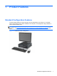
1 Product Features Standard Configuration Features The HP Compaq Small Form Factor features may vary depending on the model. For a complete listing of the hardware and software installed in the computer, run the diagnostic utility (included on some computer models only). NOTE: The Small Form Factor computer can also be used in a tower orientation. For more information, see Using the Small Form Factor Computer in a Tower Orientation on page 96 in this guide.
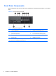
Front Panel Components Drive configuration may vary by model. Some models have a bezel blank covering one or more drive bays. Figure 1-2 Front Panel Components Table 1-1 Front Panel Components 1 5.25-inch Optical Drive 6 USB (Universal Serial Bus) Ports 2 Optical Drive Activity Light 7 Microphone Connector 3 Optical Drive Eject Button 8 3.
Rear Panel Components Figure 1-3 Rear Panel Components Table 1-2 Rear Panel Components 1 RJ-45 Network Connector 6 DVI-D Connector 2 VGA Monitor Connector 7 PS/2 Mouse Connector (green) 3 Serial Connector 8 PS/2 Keyboard Connector (purple) 4 Power Cord Connector 9 Line-Out Connector for powered audio devices (green) 5 Universal Serial Bus (USB) 10 Line-In Audio Connector (blue) NOTE: An optional second serial port and an optional parallel port are available from HP.
Serial Number Location Each computer has a unique serial number and product ID number in the location shown below. Keep these numbers available for use when contacting customer service for assistance.
2 Activating and Customizing the Software NOTE: This chapter provides information for both Windows 7 and Windows 8. Activating and customizing the software in Windows 7 If your computer was not shipped with a Windows® operating system, some portions of this documentation do not apply. Additional information is available in online help after you activate the operating system. CAUTION: Do not add optional hardware or third-party devices to the computer until the operating system is successfully activated.
Downloading Windows 7 updates Microsoft may release updates to the operating system. To help keep the computer running optimally, HP recommends checking for the latest updates during the initial installation and periodically throughout the life of the computer. 1. To set up your Internet connection, click Start > Internet Explorer and follow the instructions on the screen. 2. After an Internet connection has been established, click the Start > All Programs > Windows Update. 3.
CAUTION: After the activation process has begun, DO NOT TURN OFF THE COMPUTER UNTIL THE PROCESS IS COMPLETE. Turning off the computer during the activation process may damage the software that runs the computer or prevent its proper installation. Downloading Windows 8 updates Microsoft may release updates to the operating system. To help keep the computer running optimally, HP recommends checking for the latest updates during the initial installation and periodically throughout the life of the computer.
3 Computer Setup (F10) Utility Computer Setup (F10) Utilities Use Computer Setup (F10) Utility to do the following: 8 ● Change factory default settings. ● Set the system date and time. ● Set, view, change, or verify the system configuration, including settings for processor, graphics, memory, audio, storage, communications, and input devices. ● Modify the boot order of bootable devices such as hard drives, optical drives, or USB flash media devices.
● Solve system configuration errors detected but not automatically fixed during the Power-On SelfTest (POST). ● Replicate the system setup by saving system configuration information on a USB device and restoring it on one or more computers. ● Execute self-tests on a specified ATA hard drive (when supported by drive). ● Enable or disable DriveLock security (when supported by drive).
Computer Setup—File NOTE: Support for specific Computer Setup options may vary depending on the hardware configuration.
Computer Setup—Storage NOTE: Support for specific Computer Setup options may vary depending on the hardware configuration. Table 3-3 Computer Setup—Storage Option Description Device Configuration Lists all installed BIOS-controlled storage devices. When a device is selected, detailed information and options are displayed. The following options may be presented: ● Hard Disk: Size, model, firmware version, serial number, connector color.
Table 3-3 Computer Setup—Storage (continued) Storage Options eSATA Port Allows you to set a SATA port as an eSATA port for use with an external drive. Default is enabled. This setting affects only the port with the black connector, labeled as eSATA on the system board. This port should have the eSATA back panel connector attached to use eSATA drives. For more information, see the eSATA white paper at www.hp.com.
Table 3-3 Computer Setup—Storage (continued) DPS Self-Test Allows you to execute self-tests on ATA hard drives capable of performing the Drive Protection System (DPS) self-tests. NOTE: This selection will only appear when at least one drive capable of performing the DPS self-tests is attached to the system.
Computer Setup—Security NOTE: Support for specific Computer Setup options may vary depending on the hardware configuration. Table 3-4 Computer Setup—Security Option Description Setup Password Allows you to set and enable a setup (administrator) password. NOTE: If the setup password is set, it is required to change Computer Setup options, flash the ROM, and make changes to certain plug and play settings under Windows. Power-On Password Allows you to set and enable a power-on password.
Table 3-4 Computer Setup—Security (continued) Slot Security Allows you to disable any PCI or PCI Express slot. Default is enabled. Network Boot Enables/disables the computer’s ability to boot from an operating system installed on a network server. (Feature available on NIC models only; the network controller must be either a PCI expansion card or embedded on the system board.) Default is enabled.
Table 3-4 Computer Setup—Security (continued) System Security (these options are hardware dependent) Data Execution Prevention (enable/disable) - Helps prevent operating system security breaches. Default is enabled. SVM CPU Virtualization (enable/disable). Controls the virtualization features of the processor. Changing this setting requires turning the computer off and then back on. Default is disabled.
Table 3-4 Computer Setup—Security (continued) DriveLock Security Allows you to assign or modify a master or user password for hard drives. When this feature is enabled, the user is prompted to provide one of the DriveLock passwords during POST. If neither is successfully entered, the hard drive will remain inaccessible until one of the passwords is successfully provided during a subsequent cold-boot sequence.
Computer Setup—Power NOTE: Support for specific Computer Setup options may vary depending on the hardware configuration. Table 3-5 Computer Setup—Power Option Description OS Power Management ● Idle Power Savings—Extended/Normal. Allows certain operating systems to decrease the processors power consumption when the processor is idle. Default is extended. ● Runtime Power Management— Enable/Disable.
Computer Setup—Advanced NOTE: Support for specific Computer Setup options may vary depending on the hardware configuration. Table 3-6 Computer Setup—Advanced (for advanced users) Option Heading Power-On Options Allows you to set: ● POST mode (QuickBoot, Clear Memory, FullBoot, or FullBoot Every x Days). ◦ QuickBoot (default) = Do not clear memory or perform a memory test. ◦ FullBoot = Memory test (count) on cold boot. Clears memory on all boots. ◦ Clear Memory = No memory count on cold boot.
Table 3-6 Computer Setup—Advanced (for advanced users) (continued) BIOS Power-On Allows you to set the computer to turn on automatically at a time you specify. Onboard Devices Allows you to set resources for or disable Legacy devices. Select the Legacy device's IRQ, DMA, and I/O Range. The settings may not take effect for all operating systems. To hide a device from the operating system, see Security > Device Security.
Table 3-6 Computer Setup—Advanced (for advanced users) (continued) VGA Configuration Displayed only if there is an add-in video card in the system. Allows you to specify which VGA controller will be the “boot” or primary VGA controller. AMT Configuration Allows you to set: ● AMT (enable/disable). Allows you to enable or disable functions of the embedded Management Engine (ME) such as Active Management Technology (AMT).
4 Serial ATA (SATA) Drive Guidelines and Features NOTE: HP only supports the use of SATA hard drives on these models of computer. No Parallel ATA (PATA) drives are supported. SATA Hard Drives Serial ATA Hard Drive Characteristics Number of pins/conductors in data cable 7/7 Number of pins in power cable 15 Maximum data cable length 39.37 in (100 cm) Data interface voltage differential 400-700 mV Drive voltages 3.3 V, 5 V, 12 V Jumpers for configuring drive N/A Data transfer rate 3.
SMART ATA Drives The Self Monitoring Analysis and Recording Technology (SMART) ATA drives for the HP Personal Computers have built-in drive failure prediction that warns the user or network administrator of an impending failure or crash of the hard drive. The SMART drive tracks fault prediction and failure indication parameters such as reallocated sector count, spin retry count, and calibration retry count. If the drive determines that a failure is imminent, it generates a fault alert.
5 Identifying the Chassis, Routine Care, and Disassembly Preparation This chapter provides general service information for the computer. Adherence to the procedures and precautions described in this chapter is essential for proper service. CAUTION: When the computer is plugged into an AC power source, voltage is always applied to the system board. You must disconnect the power cord from the power source before opening the computer to prevent system board or component damage.
Electrostatic Discharge Information A sudden discharge of static electricity from your finger or other conductor can destroy static-sensitive devices or microcircuitry. Often the spark is neither felt nor heard, but damage occurs. An electronic device exposed to electrostatic discharge (ESD) may not appear to be affected at all and can work perfectly throughout a normal cycle. The device may function normally for a while, but it has been degraded in the internal layers, reducing its life expectancy.
● Always be properly grounded when touching a sensitive component or assembly. ● Avoid contact with pins, leads, or circuitry. ● Place reusable electrostatic-sensitive parts from assemblies in protective packaging or conductive foam. Personal Grounding Methods and Equipment Use the following equipment to prevent static electricity damage to equipment: ● Wrist straps are flexible straps with a maximum of one-megohm ± 10% resistance in the ground cords.
● Conductive bins and other assembly or soldering aids ● Conductive foam ● Conductive tabletop workstations with ground cord of one-megohm +/- 10% resistance ● Static-dissipative table or floor mats with hard tie to ground ● Field service kits ● Static awareness labels ● Wrist straps and footwear straps providing one-megohm +/- 10% resistance ● Material handling packages ● Conductive plastic bags ● Conductive plastic tubes ● Conductive tote boxes ● Opaque shielding bags ● Transparen
● Never cover the ventilation slots on the monitor with any type of material. ● Install or enable power management functions of the operating system or other software, including sleep states. Routine Care General Cleaning Safety Precautions 1. Never use solvents or flammable solutions to clean the computer. 2. Never immerse any parts in water or cleaning solutions; apply any liquids to a clean cloth and then use the cloth on the component. 3.
CAUTION: Use safety glasses equipped with side shields before attempting to clean debris from under the keys. ● Visible debris underneath or between the keys may be removed by vacuuming or shaking. ● Canned, pressurized air may be used to clean debris from under the keys. Caution should be used as too much air pressure can dislodge lubricants applied under the wide keys. ● If you remove a key, use a specially designed key puller to prevent damage to the keys.
Tools and Software Requirements To service the computer, you need the following: ● Torx T-15 screwdriver (HP screwdriver with bits, PN 161946-001) ● Torx T-15 screwdriver with small diameter shank (for certain front bezel removal) ● Flat-bladed screwdriver (may sometimes be used in place of the Torx screwdriver) ● Phillips #2 screwdriver ● Diagnostics software ● HP tamper-resistant T-15 wrench (Smart Cover FailSafe Key, PN 166527-001) or HP tamperresistant bits (Smart Cover FailSafe Key, PN 16652
● Before handling a drive, ensure that you are discharged of static electricity. While handling a drive, avoid touching the connector. For more information about preventing electrostatic damage, refer to Electrostatic Discharge Information on page 25 ● Do not use excessive force when inserting a drive. ● Avoid exposing a hard drive to liquids, temperature extremes, or products that have magnetic fields such as monitors or speakers.
6 Illustrated parts catalog This chapter provides parts information for the chassis.
Item Description Spare part number (1) Access panel 636924-001 (2) Front bezel 636920-001 (3) Power supply 240W, 85% efficiency 613663-001 240W, high voltage protection 613664-001 240W 613763-001 (4) Speaker, internal 636925-001 (5) System board (includes replacement thermal material) For use in models without Windows 8 676358-001 For use in models with Windows 8 Standard 676358-501 For use in models with Windows 8 Professional 676358-601 For use in models with NetClone 699943-001
Item Description Spare part number 500-GB 636929-001 500-GB, 2.5-inch, self-encrypting (SED) 696442-001 250-GB 636927-001 256-GB Solid-state drive (SSD), SATA 6.0 661842-001 680020-001 180-GB Solid-state drive (SSD), SATA 6.0 696622-001 120-GB Solid-state drive (SSD), SATA 2.
Item Description Spare part number USB (non-Windows 8) 537746-xxx USB (Windows 8) 701429-xxx USB SmartCard (non-Windows 8) 631411-xxx USB SmartCard (Windows 8) 701427-xxx Wireless (non-Windows 8) 674314-xxx Wireless (Windows 8) 701426-xxx Washable (non-Windows 8) 613125-xxx Washable (Windows 8) 700510-xxx Processors (include replacement thermal material) ● Intel Core i7 3770s processor, 3.1 GHz 689370-001 ● Intel Core i5 3570s processor, 3.
Item Description Spare part number Wireless 674317-001 USB, optical, black 537749-001 USB, laser, black 570580-001 Washable 619580-001 Wireless keyboard/mouse transceiver 674319-001 Bezel blank, 5.25-inch 570838-001 Antenna for use with WLAN module 538048-001 583345-001 Hard drive grommet 450712-001 Hard drive adapter, 2.
Spare part number Description 537745-071 Keyboard, PS/2, non-Windows 8, Spain 537745-081 Keyboard, PS/2, non-Windows 8, Denmark 537745-091 Keyboard, PS/2, non-Windows 8, Norway 537745-101 Keyboard, PS/2, non-Windows 8, Sweden 537745-111 Keyboard, PS/2, non-Windows 8, Switzerland 537745-121 Keyboard, PS/2, non-Windows 8, French Canada 537745-131 Keyboard, PS/2, non-Windows 8, Portugal 537745-141 Keyboard, PS/2, non-Windows 8, Turkey 537745-151 Keyboard, PS/2, non-Windows 8, Greece 537745-
38 Spare part number Description 537746-061 Keyboard, USB, non-Windows 8, Italy 537746-071 Keyboard, USB, non-Windows 8, Spain 537746-081 Keyboard, USB, non-Windows 8, Denmark 537746-091 Keyboard, USB, non-Windows 8, Norway 537746-101 Keyboard, USB, non-Windows 8, Sweden 537746-111 Keyboard, USB, non-Windows 8, Switzerland 537746-121 Keyboard, USB, non-Windows 8, French Canada 537746-131 Keyboard, USB, non-Windows 8, Portugal 537746-141 Keyboard, USB, non-Windows 8, Turkey 537746-151 K
Spare part number Description 603250-001 Adapter, DisplayPort (DP) to VGA 608151-001 USB 3.
40 Spare part number Description 631411-294 Keyboard, USB, SmartCard, non-Windows 8, Japan 631411-374 Keyboard, USB, SmartCard, non-Windows 8, international 631411-AA4 Keyboard, USB, SmartCard, non-Windows 8, Simplified Chinese 631411-AB4 Keyboard, USB, SmartCard, non-Windows 8, Taiwan 631411-B44 Keyboard, USB, SmartCard, non-Windows 8, International English 631411-BB4 Keyboard, USB, SmartCard, non-Windows 8, Israel 631411-DE4 Keyboard, USB, SmartCard, non-Windows 8, Arab 631411-KD4 Keyboa
Spare part number Description 657401-001 Adapter, DVI to VGA 660408-001 16X DVD±RW SuperMulti drive 661841-001 120 GB Solid-state drive (SSD), SATA 2.0 661842-001 256 GB Solid-state drive (SSD), SATA 6.0 662723-001 Adapter, DisplayPort (DP) to DVI 663213-001 USB 3.0 SuperSpeed PCI-3 x1 card, includes 2 external Type A ports and 2 internal ports 663214-001 SATA USB 3.0 SuperSpeed power extension cable, 20 in 665119-001 Intel Celeron G540 processor, 2.
42 Spare part number Description 674314-281 Keyboard, wireless, non-Windows 8, Belarus 674314-291 Keyboard, wireless, non-Windows 8, Japan 674314-371 Keyboard, wireless, non-Windows 8, international 674314-AA1 Keyboard, wireless, non-Windows 8, Simplified Chinese 674314-AB1 Keyboard, wireless, non-Windows 8, Taiwan 674314-B41 Keyboard, wireless, non-Windows 8, BHCSY 674314-BB1 Keyboard, wireless, non-Windows 8, Israel 674314-D61 Keyboard, wireless, non-Windows 8, India 674314-DE1 Keyboar
Spare part number Description 695078-001 Intel Core i5 3475s processor, 2.9 GHz 695079-001 Intel Core i5 3570s processor, 3.1 GHz 695080-001 Front bezel 696442-001 500 GB, 7200 rpm, 2.5-inch, self-encrypting (SED) hard drive 696622-001 180 GB Solid-state drive (SSD), SATA 6.
44 Spare part number Description 701426-291 Keyboard, wireless, Windows 8, Japan 701426-371 Keyboard, wireless, Windows 8, international 701426-AA1 Keyboard, wireless, Windows 8, Simplified Chinese 701426-AB1 Keyboard, wireless, Windows 8, Taiwan 701426-B41 Keyboard, wireless, Windows 8, BHCSY 701426-BB1 Keyboard, wireless, Windows 8, Israel 701426-D61 Keyboard, wireless, Windows 8, India 701426-DE1 Keyboard, wireless, Windows 8, Arab 701426-KD1 Keyboard, wireless, Windows 8, South Korea
Spare part number Description 701427-291 Keyboard, USB, Smart card, Windows 8, Japan 701427-371 Keyboard, USB, Smart card, Windows 8, international 701427-AA1 Keyboard, USB, Smart card, Windows 8, Simplified Chinese 701427-AB1 Keyboard, USB, Smart card, Windows 8, Taiwan 701427-B41 Keyboard, USB, Smart card, Windows 8, BHCSY 701427-BB1 Keyboard, USB, Smart card, Windows 8, Israel 701427-D61 Keyboard, USB, Smart card, Windows 8, India 701427-DE1 Keyboard, USB, Smart card, Windows 8, Arab 70
46 Spare part number Description 701428-291 Keyboard, PS/2, Windows 8, Japan 701428-371 Keyboard, PS/2, Windows 8, international 701428-AA1 Keyboard, PS/2, Windows 8, Simplified Chinese 701428-AB1 Keyboard, PS/2, Windows 8, Taiwan 701428-B41 Keyboard, PS/2, Windows 8, BHCSY 701428-BB1 Keyboard, PS/2, Windows 8, Israel 701428-D61 Keyboard, PS/2, Windows 8, India 701428-DE1 Keyboard, PS/2, Windows 8, Arab 701428-KD1 Keyboard, PS/2, Windows 8, South Korea 701428-L31 Keyboard, PS/2, Window
Spare part number Description 701429-291 Keyboard, USB, Windows 8, Japan 701429-371 Keyboard, USB, Windows 8, international 701429-AA1 Keyboard, USB, Windows 8, Simplified Chinese 701429-AB1 Keyboard, USB, Windows 8, Taiwan 701429-B41 Keyboard, USB, Windows 8, BHCSY 701429-BB1 Keyboard, USB, Windows 8, Israel 701429-D61 Keyboard, USB, Windows 8, India 701429-DE1 Keyboard, USB, Windows 8, Arab 701429-KD1 Keyboard, USB, Windows 8, South Korea 701429-L31 Keyboard, USB, Windows 8, Internati
7 Removal and Replacement Procedures Small Form Factor (SFF) Chassis Adherence to the procedures and precautions described in this chapter is essential for proper service. After completing all necessary removal and replacement procedures, run the Diagnostics utility to verify that all components operate properly. NOTE: Not all features listed in this guide are available on all computers. Serial Number Location Each computer has a unique serial number and product ID number in the location shown below.
3. Exit the operating system. 4. Remove any compact disc or media card from the computer. 5. Turn off the computer and any peripheral devices that are connected to it. CAUTION: Turn off the computer before disconnecting any cables. Regardless of the power-on state, voltage is always present on the system board as long as the system is plugged into an active AC outlet. In some systems the cooling fan is on even when the computer is in the “Standby,” or “Suspend” modes.
Computer Access Panel Description Spare part number Access panel 636924-001 1. Prepare the computer for disassembly (Preparation for Disassembly on page 48). 2. If the computer is on a stand, remove the computer from the stand. 3. Loosen the captive thumbscrew (1), then lift the access panel off the computer (2). Figure 7-2 Removing the Access Panel To install the access panel, reverse the removal procedure.
Front Bezel Description Spare part number Front bezel 695080-001 1. Prepare the computer for disassembly (Preparation for Disassembly on page 48). 2. Remove the access panel (Computer Access Panel on page 50). 3. Lift up the three tabs on the side of the bezel (1), then rotate the bezel off the chassis (2). Figure 7-3 Removing the Front Bezel To install the front bezel, reverse the removal procedure.
Bezel Blanks Description Spare part number 5.25-inch bezel blank 570838-001 On some models, there are bezel blanks covering the 3.5-inch and 5.25-inch external drive bays that need to be removed before installing a drive. To remove a bezel blank: 1. Remove the access panel (Computer Access Panel on page 50). 2. Remove the front bezel (Front Bezel on page 51).. 3.
System Board Connections Refer to the following illustration and table to identify the system board connectors. Figure 7-5 System Board Connections Table 7-1 System Board Connections No.
Installing Additional Memory Description Spare part number 8-GB, PC3-12800 689375-001 4-GB, PC3-12800 671613-001 2-GB, PC3-12800 671612-001 The computer comes with double data rate 3 synchronous dynamic random access memory (DDR3SDRAM) dual inline memory modules (DIMMs). DIMMs The memory sockets on the system board can be populated with up to two industry-standard DIMMs. These memory sockets are populated with at least one preinstalled DIMM.
Populating DIMM Sockets There are two DIMM sockets on the system board: XMM1 and XMM3 with one socket per Channel. XMM3 operates in memory channel A. XMM1 operates in memory Channel B. The system will automatically operate in single channel mode, dual channel mode, or flex mode, depending on how the DIMMs are installed. ● The system will operate in single channel mode if the DIMM sockets are populated in one channel only.
3. Rotate up the drive bay housing to access the memory module sockets on the system board. Figure 7-6 Rotating the Drive Cage Up 4. Open both latches of the memory module socket (1), and insert the memory module into the socket (2). Figure 7-7 Installing a DIMM NOTE: A memory module can be installed in only one way. Match the notch on the module with the tab on the memory socket. A DIMM must occupy the black XMM1 socket.
6. Rotate the drive cage back down to its normal position. Figure 7-8 Rotating the Drive Cage Down 7. Replace the access panel. 8. If the computer was on a stand, replace the stand. 9. Reconnect the power cord and turn on the computer. 10. Lock any security devices that were disengaged when the access panel was removed. The computer should automatically recognize the additional memory the next time you turn on the computer.
Description Spare part number Intel PRO/1000CT2 NIC, includes bracket 635523-001 HP FireWire / IEEE 1394a PCIe x1 Card 637591-001 Printer port 638817-001 Serial port, full height 638815-001 The computer has two PCI expansion slots, one PCI Express x1 expansion slot, and one PCI Express x16 expansion slot. NOTE: The PCI and PCI Express slots support only low profile cards. NOTE: You can install a PCI Express x1, x4, x8, or x16 expansion card in the PCI Express x16 slot.
5. Before installing an expansion card, remove the expansion slot cover or the existing expansion card. a. If you are installing an expansion card in a vacant socket, remove the appropriate expansion slot cover on the back of the chassis. Pull the slot cover straight up then away from the inside of the chassis.
b. If you are removing a standard PCI card or PCI Express x1 card, hold the card at each end, and carefully rock it back and forth until the connectors pull free from the socket. Pull the expansion card straight up from the socket (1) then away from the inside of the chassis to release it from the chassis frame (2). Be sure not to scrape the card against the other components. NOTE: Before removing an installed expansion card, disconnect any cables that may be attached to the expansion card.
c. If you are removing a PCI Express x16 card, pull the retention arm on the back of the expansion socket away from the card and carefully rock the card back and forth until the connectors pull free from the socket. Pull the expansion card straight up from the socket then away from the inside of the chassis to release it from the chassis frame. Be sure not to scrape the card against the other components. Figure 7-12 Removing a PCI Express x16 Expansion Card 6.
8. To install a new expansion card, hold the card just above the expansion socket on the system board then move the card toward the rear of the chassis (1) so that the bracket on the card is aligned with the open slot on the rear of the chassis. Press the card straight down into the expansion socket on the system board (2). Figure 7-13 Installing an Expansion Card NOTE: When installing an expansion card, press firmly on the card so that the whole connector seats properly in the expansion card slot. 9.
13. Reconnect the power cord and turn on the computer. 14. Lock any security devices that were disengaged when the access panel was removed. 15. Reconfigure the computer, if necessary.
Cable Management The Small Form Factor chassis is a very compact computer and proper routing of the internal cables is critical to the operation of the computer. Follow good cable management practices when working inside the computer. ● Keep cables away from major heat sources like the heat sink. ● Do not jam cables on top of expansion cards or memory modules. Printed circuit cards like these are not designed to take excessive pressure on them.
Drives Description Spare part number Optical drives: 6X BD-Writer SuperMulti drive 656792-001 16X DVD±RW SuperMulti drive 690418-001 660408-001 16X DVD-ROM drive 682550-001 Hard drives: 1 TB hard drive 636930-001 500 GB hard drive 636929-001 500 GB, 2.5-inch, self-encrypting (SED) hard drive 696442-001 250 GB hard drive 636927-001 256 GB Solid-state drive (SSD), SATA 6.0 661842-001 680020-001 180 GB Solid-state drive (SSD), SATA 6.0 696622-001 120 GB Solid-state drive (SSD), SATA 2.
Drive Positions Figure 7-15 Drive Positions Table 7-2 Drive Positions 1 3.5-inch internal hard drive bay 2 3.5-inch internal drive bay for optional drives (media card reader shown) 3 5.25-inch internal drive bay for optional drives (optical drive shown) NOTE: The drive configuration on your computer may be different than the drive configuration shown above. To verify the type, size, and capacity of the storage devices installed in the computer, run Computer Setup.
NOTE: If you are replacing the primary hard drive, you must remove the four silver and blue 6-32 isolation mounting screws from the old hard drive and install them in the new hard drive. Figure 7-16 Extra Mounting Screw Locations Table 7-3 Extra Mounting Screws No. Mounting Screw Device 1 Black M3 Metric Screws All Drives (except hard drives) 2 Silver 6-32 Standard Screws Secondary Hard Drive (in systems supporting two hard drives) There are a total of five extra silver 6-32 standard screws.
Removing an Internal 5.25-inch Drive CAUTION: All removable media should be taken out of a drive before removing the drive from the computer. To remove a 5.25-inch internal drive: 1. Prepare the computer for disassembly (Preparation for Disassembly on page 48). 2. Remove the access panel (Computer Access Panel on page 50). 3. Rotate the drive cage to its upright position (1) and remove the mounting screw on the back left side of the drive (2). Figure 7-17 Removing the Drive Mounting Screw 4.
5. Rotate the drive cage back down to its normal position. CAUTION: Be careful not to pinch any cables or wires when rotating the drive cage down. Figure 7-19 Rotating the Drive Cage Down 6. Slide the drive back until it stops, then lift it up and out of the drive cage. Figure 7-20 Removing the 5.25-inch Drive NOTE: When replacing a drive, transfer the four mounting screws from the old drive to the new one.
Installing an Optical Drive into the 5.25-inch Drive Bay To install an optional 5.25-inch optical drive: 1. Prepare the computer for disassembly (Preparation for Disassembly on page 48). 2. Remove the access panel (Computer Access Panel on page 50). 3. If you are installing a drive in a bay covered by a bezel blank, remove the front bezel then remove the bezel blank. See Bezel Blanks on page 52 for more information. 4.
6. Rotate the drive cage to its upright position (1) and install an M3 mounting screw in the back left side of the drive (2) to secure the drive to the drive cage. Figure 7-23 Securing the Drive in the Drive Cage 7. Connect the SATA data cable to the white system board connector labeled SATA1 if it is not already connected. 8. Route the data cable through the cable guides. CAUTION: There are two cable guides that keep the data cable from being pinched by the drive cage when raising or lowering it.
10. Rotate the drive cage back down to its normal position. CAUTION: Be careful not to pinch any cables or wires when rotating the drive cage down. Figure 7-25 Rotating the Drive Cage Down 11. Replace the access panel. 12. If the computer was on a stand, replace the stand. 13. Reconnect the power cord and turn on the computer. 14. Lock any security devices that were disengaged when the access panel was removed. The system automatically recognizes the drive and reconfigures the computer.
2. If you are removing a media card reader, disconnect the USB cable from the system board. Figure 7-26 Disconnecting the Media Card Reader USB Cable 3. Rotate the drive cage to its upright position (1) and remove the mounting screw on the back left side of the drive (2). Figure 7-27 Removing the Drive Mounting Screw 4. Rotate the drive cage back down to its normal position.
5. Slide the drive back until it stops, then lift it up and out of the drive cage. Figure 7-29 Removing a 3.5-inch Drive (Media Card Reader Shown) NOTE: When replacing a 3.5-inch drive, transfer the four mounting screws from the old drive to the new one. Installing a Drive into the 3.5-inch Internal Drive Bay The 3.5-inch bay is located underneath the 5.25-inch drive. To install a drive into the 3.5-inch bay: 1. Follow the procedure in Removing an Internal 5.25-inch Drive on page 68 to remove the 5.
4. Position the mounting screws on the drive into the J-slots in the drive bay. Then slide the drive toward the front of the computer until it stops. Figure 7-31 Installing a Drive into the 3.5-inch Drive Bay (Media Card Reader Shown) 5. Rotate the drive cage to its upright position (1) and install an M3 mounting screw in the back left side of the drive (2) to secure the drive to the drive cage. Figure 7-32 Securing the Drive in the Drive Cage 6. Rotate the drive cage back down to its normal position.
7. If installing a media card reader, connect the USB cable from the media card reader to the USB connector on the system board labeled MEDIA1. Figure 7-34 Connecting the Media Card Reader USB Cable NOTE: Refer to System Board Connections on page 53 for an illustration of the system board drive connectors. 8. Replace the 5.25-inch drive. 9. Replace the access panel. 10. If the computer was on a stand, replace the stand. 11. Reconnect the power cord and turn on the computer. 12.
Removing and Replacing the Primary 3.5-inch Internal SATA Hard Drive NOTE: Before you remove the old hard drive, be sure to back up the data from the old hard drive so that you can transfer the data to the new hard drive. The preinstalled 3.5-inch hard drive is located under the power supply. To remove and replace the hard drive: 1. Prepare the computer for disassembly (Preparation for Disassembly on page 48). 2. Remove the access panel (Computer Access Panel on page 50). 3.
5. Press and hold down the latch to disconnect the power cable (1) and data cable (2) from the back of the hard drive. Figure 7-37 Disconnecting the Hard Drive Power Cable and Data Cable 6. Press down on the green release latch next to the hard drive (1). While holding the latch down, slide the drive forward until it stops, then lift the drive up and out of the bay (2). Figure 7-38 Removing the Hard Drive 7.
8. Align the mounting screws with the slots on the chassis drive cage, press the hard drive down into the bay, then slide it back until it stops and locks in place. Figure 7-40 Installing the Hard Drive 9. Connect the power and data cables to the back of the hard drive. NOTE: When replacing the primary hard drive, be sure to route the SATA and power cables through the cable guide on the bottom of the chassis frame behind the hard drive.
Baffle Description Spare part number Baffle 636921-001 The baffle sits between the front fan and the heat sink. 1. Prepare the computer for disassembly (Preparation for Disassembly on page 48). 2. Remove the access panel (Computer Access Panel on page 50). 3. Remove the cables from the holder on the side of the baffle. 4. Lift the baffle straight up out of the chassis. Figure 7-41 Removing the baffle To install the baffle, reverse the removal procedure.
Front Fan Assembly Description Spare part number Front fan assembly 636922-001 The front fan assembly is attached to the front of the chassis. 1. Prepare the computer for disassembly (Preparation for Disassembly on page 48). 2. Remove the access panel (Computer Access Panel on page 50). 3. Remove the front bezel (Front Bezel on page 51). 4. Remove the baffle (Baffle on page 80). 5. Disconnect the fan cable from the red/brown system board connector labeled CHFAN. 6.
Front I/O, Power Switch Assembly Description Spare part number Front I/O and power switch assembly 636926-001 The front I/O and power switch/LEDs are one assembly, attached to the front of the chassis. Push the assembly into the chassis to remove. 1. Prepare the computer for disassembly (Preparation for Disassembly on page 48). 2. Remove the access panel (Computer Access Panel on page 50). 3. Remove the front bezel (Front Bezel on page 51). 4.
8. Route the cables through the slots beneath the drive cage, pull the assembly (right side first) into the chassis, and then remove the assembly from the computer. Figure 7-45 Routing the cables and removing the power switch assembly To install the front I/O and power switch assembly, reverse the removal procedure. NOTE: Be sure to correctly route the cables beneath the drive cage when reinstalling the assembly.
7. Lift the speaker from the inside of the chassis to remove it (2). Figure 7-46 Removing the speaker To install the speaker, reverse the removal procedures. Heat sink Description Spare part number Heat sink 636919-001 The heat sink is secured atop the processor with four captive Torx screws. The heat sink does not include a fan. 84 1. Prepare the computer for disassembly (Preparation for Disassembly on page 48). 2. Remove the access panel (Computer Access Panel on page 50). 3.
5. Loosen the four captive screws that secure the heat sink to the system board tray. CAUTION: Heat sink retaining screws should be removed in diagonally opposite pairs (as in an X) to even the downward forces on the processor. This is especially important as the pins on the socket are very fragile and any damage to them may require replacing the system board.
6. Lift the heat sink from atop the processor and set it on its side to keep from contaminating the work area with thermal grease. Figure 7-48 Removing the heat sink When reinstalling the heat sink, make sure that its bottom has been cleaned with an alcohol wipe and fresh thermal grease has been applied to the top of the processor.
Processor Description Spare part number Intel Core i7 3770s processor, 3.1 GHz 689370-001 Intel Core i5 3570s processor, 3.1 GHz 695079-001 Intel Core i5 3475s processor, 2.9 GHz 695078-001 Intel Core i5 3470s processor, 2.9 GHz 695077-001 Intel Core i3 3240 processor, 3.4 GHz 688951-001 Intel Core i3 3225 processor, 3.3 GHz 689578-001 Intel Core i3 3220 processor, 3.3 GHz 688950-001 Intel Core i3 3210 processor, 3.2 GHz 715895-001 Intel Core i3 2130 processor, 3.
7. Carefully lift the processor from the socket (3). CAUTION: Do NOT handle the pins in the processor socket. These pins are very fragile and handling them could cause irreparable damage. Once pins are damaged it may be necessary to replace the system board. The heat sink must be installed within 24 hours of installing the processor to prevent damage to the processor’s solder connections. Figure 7-49 Removing the processor To install a new processor: 1.
6. If using a new heat sink, remove the protective covering from the bottom of the heat sink and place it in position atop the processor. 7. Secure the heat sink to the system board and system board tray with the four captive screws and attach the heat sink control cable to the system board. CAUTION: heat sink retaining screws should be tightened in diagonally opposite pairs (as in an X) to evenly seat the heat sink on the processor.
7. Pull the power supply forward (1) until the posts (2) on the power supply move forward in the power supply bracket, and then lift the power supply straight up and out of the chassis. Figure 7-50 Removing the power supply Use the following table to determine the correct power supply/system board connections.
System Board NOTE: All system board spare part kits come with replacement thermal material. Description Spare part number System board for use in models without Windows 8 676358-001 System board for use in models with Windows 8 Standard 676358-501 System board for use in models with Windows 8 Professional 676358-601 System board for use in models with NetClone 699943-001 1. Prepare the computer for disassembly (Preparation for Disassembly on page 48). 2.
11. Slide the system board toward the front of the chassis (2), and then lift the rear of the system board up and out of the chassis (3). Figure 7-51 Removing the system board To install the system board, reverse the removal procedure. NOTE: BIOS. When replacing the system board, you must also change the chassis serial number in the CAUTION: Before reinstalling the heat sink you must clean the top of the processor and the bottom of the heat sink with an alcohol pad supplied in the spares kit.
Battery The battery that comes with your computer provides power to the real-time clock and has a lifetime of about three years. When replacing the battery, use a battery equivalent to the battery originally installed on the computer. The computer comes with a 3-volt lithium coin cell battery. NOTE: The lifetime of the lithium battery can be extended by plugging the computer into a live AC wall socket. The lithium battery is only used when the computer is NOT connected to AC power.
Type 1 Battery Holder 1. Lift the battery out of its holder. Figure 7-52 Removing the battery from a type 1 holder 2. Slide the replacement battery into position, positive side up. 3. The battery holder automatically secures the battery in the proper position. 4. Replace the computer access panel. 5. Plug in the computer and turn on power to the computer. 6. Reset the date and time, your passwords, and any special system setups, using Computer Setup.
3. Replace the computer access panel. 4. Plug in the computer and turn on power to the computer. 5. Reset the date and time, your passwords, and any special system setups, using Computer Setup. Refer to Computer Setup (F10) Utility on page 8. Type 3 Battery Holder 1. Pull back on the clip (1) that holds the battery in place, then remove the battery (2). 2. Insert the new battery and position the clip back in place. Figure 7-54 Removing the battery from a type 3 holder 3.
Using the Small Form Factor Computer in a Tower Orientation The Small Form Factor computer can be used in a tower orientation. The HP logo plate on the front bezel is adjustable for either desktop or tower orientation. 1. Prepare the computer for disassembly (Preparation for Disassembly on page 48). 2. Orient the computer so that its right side is facing down and place the computer in the optional stand.
Installing a Security Lock The security locks displayed below and on the following pages can be used to secure the computer.
Padlock Figure 7-57 Installing a Padlock 98 Chapter 7 Removal and Replacement Procedures Small Form Factor (SFF) Chassis
Front Bezel Security The front bezel can be locked in place by installing a security screw provided by HP. To install the security screw: 1. Remove/disengage any security devices that prohibit opening the computer. 2. Remove all removable media, such as compact discs or USB flash drives, from the computer. 3. Turn off the computer properly through the operating system, then turn off any external devices. 4. Disconnect the power cord from the power outlet and disconnect any external devices.
9. Install the security screw next to the middle front bezel release tab to secure the front bezel in place. Figure 7-59 Installing the Front Bezel Security Screw 10. Replace the access panel. 11. If the computer was on a stand, replace the stand. 12. Reconnect the power cord and turn on the computer. 13. Lock any security devices that were disengaged when the access panel was removed.
A Power Cord Set Requirements The power supplies on some computers have external power switches. The voltage select switch feature on the computer permits it to operate from any line voltage between 100-120 or 220-240 volts AC. Power supplies on those computers that do not have external power switches are equipped with internal switches that sense the incoming voltage and automatically switch to the proper voltage.
Country-Specific Requirements Additional requirements specific to a country are shown in parentheses and explained below. Country Accrediting Agency Country Accrediting Agency Australia (1) EANSW Italy (1) IMQ Austria (1) OVE Japan (3) METI Belgium (1) CEBC Norway (1) NEMKO Canada (2) CSA Sweden (1) SEMKO Denmark (1) DEMKO Switzerland (1) SEV Finland (1) SETI United Kingdom (1) BSI France (1) UTE United States (2) UL Germany (1) VDE 1.
B POST Error Messages This appendix lists the error codes, error messages, and the various indicator light and audible sequences that you may encounter during Power-On Self-Test (POST) or computer restart, the probable source of the problem, and steps you can take to resolve the error condition. POST Message Disabled suppresses most system messages during POST, such as memory count and non-error text messages. If a POST error occurs, the screen will display the error message.
POST Numeric Codes and Text Messages This section covers those POST errors that have numeric codes associated with them. The section also includes some text messages that may be encountered during POST. NOTE: The computer will beep once after a POST text message is displayed on the screen. Table B-1 Numeric Codes and Text Messages Control panel message Description Recommended action ERROR: No boot disk has been detected or the disk has failed. The computer cannot read the boot sector of the boot disk.
Interpreting POST Diagnostic Front Panel LEDs and Audible Codes This section covers the front panel LED codes as well as the audible codes that may occur before or during POST that do not necessarily have an error code or text message associated with them. WARNING! When the computer is plugged into an AC power source, voltage is always applied to the system board.
Table B-2 Diagnostic Front Panel LEDs and Audible Codes (continued) Activity Blinks Possible Cause Recommended Action Red Power LED flashes four times, once every second, followed by a two second pause. Beeps stop after fifth iteration but LEDs continue until problem is solved. 4 Power failure (power supply is overloaded). 1. Open the hood and ensure the 4 or 6-wire power supply cable is seated into the connector on the system board. 2.
C Troubleshooting Without Diagnostics This chapter provides information on how to identify and correct minor problems, such as USB devices, hard drive, optical drive, graphics, audio, memory, and software problems. If you encounter problems with the computer, refer to the tables in this chapter for probable causes and recommended solutions.
● Refer to the comprehensive online technical support at http://www.hp.com/support. ● Refer to Helpful Hints on page 108 in this guide. To assist you in resolving problems online, HP Instant Support Professional Edition provides you with self-solve diagnostics. If you need to contact HP support, use HP Instant Support Professional Edition's online chat feature. Access HP Instant Support Professional Edition at: http://www.hp.com/ go/ispe. Access the Business Support Center (BSC) at http://www.hp.
● Wake the computer by pressing any key on the keyboard or pressing the power button. If the system remains in suspend mode, shut down the computer by pressing and holding the power button for at least four seconds then press the power button again to restart the computer. If the system will not shut down, unplug the power cord, wait a few seconds, then plug it in again. The computer will restart if it is set to power on automatically as soon as power is restored in Computer Setup.
Solving General Problems You may be able to easily resolve the general problems described in this section. If a problem persists and you are unable to resolve it yourself or if you feel uncomfortable about performing the operation, contact an authorized dealer or reseller. WARNING! When the computer is plugged into an AC power source, voltage is always applied to the system board.
Cursor will not move using the arrow keys on the keypad. Cause Solution The Num Lock key is turned on. Press the Num Lock key. The Num Lock light must be off if you want to use the arrow keys on the keypad. You can also disable or enable the Num Lock key in Computer Setup at Advanced > Device Options. There is no sound or sound volume is too low. Cause Solution System volume may be set low or muted. 1.
Table C-1 Solving General Problems (continued) Poor performance. Cause Solution Virus resident on the hard drive. Run virus protection program. Too many applications running. Windows 7: 1. Close unnecessary applications to free up memory. 2. Add more memory. 3. Some applications run in the background and can be closed by right-clicking on their corresponding icons in the task tray. To prevent these applications from launching at startup: In Windows 7: a.
Computer powered off automatically and the Power LED flashes Red two times, once every second, followed by a two second pause, and the computer beeps two times. (Beeps stop after fifth iteration but LEDs continue flashing). Cause Solution Processor thermal protection activated: 1. Ensure that the computer air vents are not blocked and the processor cooling fan is running. 2. Open the access panel, press the power button, and see if the processor fan (or other system fan) spins.
Solving Power Problems Common causes and solutions for power problems are listed in the following table. Table C-2 Solving Power Problems Power supply shuts down intermittently. Cause Solution If equipped with a voltage selector, voltage selector switch on rear of computer chassis (some models) not switched to correct line voltage (115V or 230V). Select the proper AC voltage using the selector switch. Power supply will not turn on because of internal power supply fault. Replace the power supply.
Power LED flashes Red four times, once every second, followed by a two second pause, and the computer beeps four times. (Beeps stop after fifth iteration but LEDs continue flashing.) Cause Solution Power failure (power supply is overloaded). 1. If equipped with a voltage selector, check that the voltage selector, located on the rear of the power supply (some models), is set to the appropriate voltage. Proper voltage setting depends on your region. 2.
Solving Hard Drive Problems Table C-3 Solving Hard Drive Problems Hard drive error occurs. Cause Solution Hard disk has bad sectors or has failed. 1. In Windows 7, click Start, click Computer, and rightclick on a drive. Select Properties, and then select the Tools tab. Under Error-checking click Check Now. In Windows 8, on the Start screen type e, and then select File Explorer from the list of applications.
Nonsystem disk/NTLDR missing message. Cause Solution The system is trying to start from the hard drive but the hard drive may have been damaged. 1. Perform Drive Protection System (DPS) testing in system ROM. System files missing or not properly installed. 1. Insert bootable media and restart the computer. 2. Boot to the windows installation media and select the recovery option. If only a restore kit is available, then select the File Backup Program option, and then restore the system. 3.
Computer seems to be locked up. Cause Solution Program in use has stopped responding to commands. 1. Use the task manager to close programs that do not respond. 2. Attempt the normal Windows “Shut Down” procedure. If this fails, press the power button for four or more seconds to turn off the power. To restart the computer, press the power button again.
Solving Media Card Reader Problems Table C-4 Solving Media Card Reader Problems Media card will not work in a digital camera after formatting it in Windows. Cause Solution By default, Windows will format any media card with a capacity greater than 32MB with the FAT32 format. Some digital cameras use the FAT (FAT16 & FAT12) format and can not operate with a FAT32 formatted card.
Do not know how to remove a media card correctly. Cause Solution The computer’s software is used to safely eject the card. In Windows 7, click Start, select Computer, right-click on the corresponding drive icon, and then select Eject. Pull the card out of the slot. In Windows 8, on the Start screen, type e, and then click File Explorer from the list of applications. Expand Computer, right-click on the corresponding drive icon, and then select Eject. Pull the card out of the slot.
Solving Display Problems If you encounter display problems, see the documentation that came with the monitor and to the common causes and solutions listed in the following table. Table C-5 Solving Display Problems Blank screen (no video). Cause Solution Monitor is not turned on and the monitor light is not on. Turn on the monitor and check that the monitor light is on. Bad monitor. Try a different monitor. The cable connections are not correct.
Blank screen and the power LED flashes Red five times, once every second, followed by a two second pause, and the computer beeps five times. (Beeps stop after fifth iteration but LEDs continue flashing.) Cause Solution Pre-video memory error. 1. Reseat DIMMs. Power on the system. 2. Replace DIMMs one at a time to isolate the faulty module. 3. Replace third-party memory with HP memory. 4. Replace the system board.
Blurry video or requested resolution cannot be set. Cause Solution If the graphics controller was upgraded, the correct graphics drivers may not be loaded. Install the video drivers included in the upgrade kit. Monitor is not capable of displaying requested resolution. Change requested resolution. Graphics card is bad. Replace the graphics card. The picture is broken up, rolls, jitters, or flashes. Cause Solution The monitor connections may be incomplete or the monitor may be incorrectly adjusted.
“Out of Range” displays on screen. Cause Solution Video resolution and refresh rate are set higher than what the monitor supports. Restart the computer and enter Safe Mode. Change the settings to a supported setting then restart the computer so that the new settings take effect. To enter Safe Mode in Windows 7: 1. Restart the computer. 2. Press and hold the F8 key as your computer restarts, before the Windows logo appears. If the Windows logo appears, you must restart the computer and try again. 3.
Fuzzy focus; streaking, ghosting, or shadowing effects; horizontal scrolling lines; faint vertical bars; or unable to center the picture on the screen (flat panel monitors using an analog VGA input connection only). Cause Solution Flat panel monitor’s internal digital conversion circuits may be unable to correctly interpret the output synchronization of the graphics card. 1. Select the monitor’s Auto-Adjustment option in the monitor’s on-screen display menu. 2.
Solving Audio Problems If the computer has audio features and you encounter audio problems, see the common causes and solutions listed in the following table. Table C-6 Solving Audio Problems Sound cuts in and out. Cause Solution Processor resources are being used by other open applications. Shut down all open processor-intensive applications. Sound does not come out of the speaker or headphones. Cause Solution Software volume control is turned down or muted.
Table C-6 Solving Audio Problems (continued) Sound does not come out of the speaker or headphones. Cause Solution Some applications can select which audio output device is used. Make sure the application has selected the correct audio device. The operating system controls may be set to use a different audio device as the default output device than what is expected. Set the operating system to use the correct audio device. Sound from headphones is not clear or muffled.
Table C-6 Solving Audio Problems (continued) There is no sound or sound volume is too low. Cause Solution Some applications can select which audio output device is used. Make sure the application has selected the correct audio device. The operating system controls may be set to use a different audio device as the default output device than what is expected. Set the operating system to use the correct audio device.
Table C-7 Solving Printer Problems (continued) Printer prints garbled information. Cause Solution The cables may not be connected properly. Reconnect all cables. Printer memory may be overloaded. Reset the printer by turning it off for one minute, then turn it back on. Printer will not print. Cause Solution The printer may be out of paper. Check the paper tray and refill it if it is empty.
Solving Keyboard and Mouse Problems If you encounter keyboard or mouse problems, see the documentation that came with the equipment and to the common causes and solutions listed in the following table. Table C-8 Solving Keyboard Problems A wireless keyboard/mouse is not working correctly. Symptoms include lagging mouse movement, jumpy mouse/ keyboard, or no function of mouse/keyboard and external drive. Cause Solution If your computer is equipped with USB 3.0 ports, connected USB 3.
Table C-9 Solving Mouse Problems Mouse does not respond to movement or is too slow. Cause Solution Mouse connector is not properly plugged into the back of the computer. Shut down the computer using the keyboard. Windows 7: 1. Press the Ctrl and Esc keys at the same time (or press the Windows logo key) to display the Start menu. 2. Use the arrow keys to select Shut Down and then press Enter. 3.
Solving Hardware Installation Problems You may need to reconfigure the computer when you add or remove hardware, such as an additional drive or expansion card. If you install a plug and play device, Windows automatically recognizes the device and configures the computer. If you install a non-plug and play device, you must reconfigure the computer after completing installation of the new hardware. In Windows, use the Add Hardware Wizard and follow the instructions that appear on the screen.
Computer will not start. Cause Solution Wrong memory modules were used in the upgrade or memory modules were installed in the wrong location. 1. Review the documentation that came with the system to determine if you are using the correct memory modules and to verify the proper installation. NOTE: DIMM1 or XMM1 must always be installed. On all computers except the USDT, DIMM1 must be installed before DIMM2, and DIMM3 must be installed before DIMM4. 2.
Power LED flashes Red ten times, once every second, followed by a two second pause, and the computer beeps ten times. (Beeps stop after fifth iteration but LEDs continue flashing.) Cause Solution Bad option card. 1. Check each option card by removing the cards one at time (if multiple cards), then power on the system to see if fault goes away. 2. Once bad card is identified, remove and replace bad option card. 3. Replace the system board.
Network driver does not detect network controller. Cause Solution Network controller is disabled. 1. Run Computer Setup and enable network controller. 2. Enable the network controller in the operating system using Device Manager. To access Device Manager in Windows 7, click Start, select Control Panel, and then select Device Manager. To access Device Manager in Windows 8, from the Start screen, type c, select Control Panel from the list of applications, and then select Device Manager.
Diagnostics reports a failure. Cause Solution The cable is not securely connected. Ensure that the cable is securely attached to the network connector and that the other end of the cable is securely attached to the correct device. The cable is attached to the incorrect connector. Ensure that the cable is attached to the correct connector. There is a problem with the cable or a device at the other end of the cable. Ensure that the cable and device at the other end are operating correctly.
Table C-11 Solving Network Problems (continued) Network controller stops working without apparent cause. Cause Solution The cable is not securely connected. Ensure that the cable is securely attached to the network connector and that the other end of the cable is securely attached to the correct device. The network controller is defective. Contact an authorized service provider. New network card will not boot.
Table C-12 Solving Memory Problems System will not boot or does not function properly after installing additional memory modules. Cause Solution A memory module is not installed in the DIMM1 or XMM1 socket. Ensure that a memory module is installed in the DIMM1 or XMM1 socket on the system board. This socket must be populated with a memory module. Memory module is not the correct type or speed grade for the system or the new memory module is not seated properly.
Solving Processor Problems If you encounter processor problems, common causes and solutions are listed in the following table. Table C-13 Solving Processor Problems Poor performance is experienced. Cause Solution Processor is hot. 1. Make sure the airflow to the computer is not blocked. 2. Make sure the fans are connected and working properly (some fans only operate when needed). 3. Make sure the processor heat sink is installed properly.
Table C-14 Solving CD-ROM and DVD Problems (continued) System will not boot from CD-ROM or DVD drive. Cause Solution Network Boot is enabled in Computer Setup. Run the Computer Setup utility and disable Network Boot in Security > Network Boot. Non-bootable CD in drive. Try a bootable CD in the drive. Boot order not correct. Run the Computer Setup utility and change boot sequence in Storage > Boot Order. Drive not found (identified). Cause Solution Cable could be loose. Check cable connections.
Cannot eject compact disc (tray-load unit). Cause Solution Disc not properly seated in the drive. Turn off the computer and insert a thin metal rod into the emergency eject hole and push firmly. Slowly pull the tray out from the drive until the tray is fully extended, then remove the disc. CD-ROM, CD-RW, DVD-ROM, or DVD-R/RW drive cannot read a disc or takes too long to start. Cause Solution Media is corrupt. Try different media to confirm whether media is valid. Media has been inserted upside down.
Table C-15 Solving USB Flash Drive Problems USB flash drive is not seen as a drive letter in Windows. Cause Solution The drive letter after the last physical drive is not available. Change the default drive letter for the flash drive in Windows. USB flash drive not found (identified). Cause Solution The device is attached to a USB port that has been hidden in Computer Setup. Run the Computer Setup utility and enable USB ports in Security > USB Security.
Solving Front Panel Component Problems If you encounter problems with devices connected to the front panel, refer to the common causes and solutions listed in the following table. A USB device, headphone, or microphone is not recognized by the computer. Cause Solution Device is not properly connected. 1. Turn off the computer. 2. Reconnect the device to the front of the computer and restart the computer. The device does not have power.
Unable to connect to the Internet. Cause Solution IP address is not configured properly. Contact your ISP for the correct IP address. Cookies are corrupted. (A “cookie” is a small piece of information that a Web server can store temporarily with the Web browser. This is useful for having the browser remember some specific information that the Web server can later retrieve.) Windows 7: 1. Select Start > Control Panel. 2. Click Internet Options. 3.
Solving Software Problems Most software problems occur as a result of the following: ● The application was not installed or configured correctly. ● There is insufficient memory available to run the application. ● There is a conflict between applications. ● Be sure that all the needed device drivers have been installed. ● If you have installed an operating system other than the factory-installed operating system, check to be sure it is supported on the system.
Computer will not continue after HP logo screen displays. Cause Solution System files may be damaged. In Windows 7, use recovery media to scan hard drive for errors, or use Windows Startup Repair to fix problems that might prevent Windows from starting correctly. Windows Startup Repair is one of the recovery tools in the System Recovery Options menu. You can also create a system repair disc that contains the System Recovery Options menu.
Contacting Customer Support For help and service, contact an authorized reseller or dealer. To locate a reseller or dealer near you, visit http://www.hp.com. NOTE: If you take the computer to an authorized reseller, dealer, or service provider for service, remember to provide the setup and power-on passwords if they are set. Refer to the number listed in the warranty or in the Support Telephone Numbers guide for technical assistance.
D HP PC Hardware Diagnostics Use the UEFI-based hardware diagnostic solution that HP includes on all products to diagnose hardware issues. You can use this tool even if the computer will not boot to the operating system. This tool also works with components not diagnosed in HPSA. Why run HP PC Hardware Diagnostics The HP PC Hardware Diagnostic tools simplify the process of diagnosing hardware issues and expedite the support process when issues are found.
How to access and run HP PC Hardware Diagnostics You can run the diagnostics from one of three places, depending on your preference and the health of the computer. 1. Turn on the computer and press Esc repeatedly until the BIOS Boot Menu appears. 2. Press F2 or select Diagnostics (F2). Pressing F2 signals the system to search for the diagnostics in the following locations: a.
Downloading HP PC Hardware Diagnostics to a USB device 1. Go to http://www.hp.com. 2. Click the Support & Drivers link. 3. Select the Drivers & Software tab. 4. Enter the product name in the text box and click Search. 5. Select your specific computer model. 6. Select your operating system. 7. In the Diagnostic section, click the HP UEFI Support Environment link. This link provides additional information. - or Click the Download button and select Run.
E Backup and Recovery Restoring and recovering in Windows 7 To protect from loss or damage, back up your personal data files. Refer to the operating system or backup utility documentation for instructions on making backup copies of your data files. To protect the software from loss or damage, keep a backup copy of all system software, applications, and related files stored on the hard drive. If you cannot create system recovery CDs or DVDs, you can order a recovery disk set from support.
System Recovery completely erases and reformats the hard disk drive, deleting all data files that you have created, and then reinstalls the operating system, programs, and drivers. However, you must reinstall any software that was not installed on the computer at the factory. This includes software that came on media included in the computer accessory box, and any software programs you installed after purchase. NOTE: Always use the System Restore procedure before you use the System Recovery program.
8. System Recovery begins. After System Recovery is complete, click Finish to restart the computer. 9. When Windows has loaded, shut down the computer, reconnect all peripheral devices, and then turn the computer back on. System Recovery when Windows is not responding CAUTION: System Recovery deletes all data and programs you created or installed. If Windows is not responding, but the computer is working, follow these steps to perform a System Recovery. 1. Turn off the computer.
● If you are creating recovery discs, be sure to use high-quality discs. It is normal for the system to reject defective discs. You will be prompted to insert a new blank disc to try again. ● The number of discs in the recovery-disc set depends on your computer model (typically 3 to 6 DVDs). The Recovery Media Creation program tells you the specific number of blank discs needed to make the set.
Using recovery media CAUTION: System Recovery deletes all data and programs you have created or installed. Back up any important data to a CD or DVD or to a USB flash drive. To create recovery media, see System recovery using recovery media on page 153. To perform a System Recovery using recovery media: 1. If using a set of DVDs, insert the first recovery disc into the DVD drive tray, and close the tray. If you are using a recovery USB flash drive, insert it into a USB port. 2.
Backup and recovery in Windows 8 To protect your information, use Windows Backup and Restore to back up individual files and folders, back up your entire hard drive, create system repair media, or create system restore points. In case of system failure, you can use the backup files to restore the contents of your computer. From the Start screen, type restore, click Settings, and then select from the list of displayed options.
Performing a system recovery In case of system failure or instability, the computer provides the following tools to recover your files: ● Windows recovery tools: You can use Windows Backup and Restore to recover information you have previously backed up. You can also use Windows Automatic Repair to fix problems that might prevent Windows from starting correctly. ● f11 recovery tools: You can use the f11 recovery tools to recover your original hard drive image.
Using f11 recovery tools CAUTION: Using f11 completely erases hard drive contents and reformats the hard drive. All files that you have created and any software that you have installed on the computer are permanently removed. The f11 recovery tool reinstalls the operating system and HP programs and drivers that were installed at the factory. Software not installed at the factory must be reinstalled. To recover the original hard drive image using f11: 1. If possible, back up all personal files. 2.
F Password Security and Resetting CMOS This computer supports security password features, which can be established through the Computer Setup Utilities menu. This computer supports two security password features that are established through the Computer Setup Utilities menu: setup password and power-on password. When you establish only a setup password, any user can access all the information on the computer except Computer Setup.
Resetting the Password Jumper To disable the power-on or setup password features, or to clear the power-on or setup passwords, complete the following steps: 1. Shut down the operating system properly, then turn off the computer and any external devices, and disconnect the power cord from the power outlet. 2. With the power cord disconnected, press the power button again to drain the system of any residual power.
Clearing and Resetting the CMOS The computer’s configuration memory (CMOS) stores information about the computer’s configuration. 1. Turn off the computer and any external devices, and disconnect the power cord from the power outlet. 2. Disconnect the keyboard, monitor, and any other external equipment connected to the computer.
6. Reconnect the external devices. 7. Plug in the computer and turn on power. NOTE: You will receive POST error messages after clearing CMOS and rebooting advising you that configuration changes have occurred. Use Computer Setup to reset any special system setups along with the date and time.
G Drive Protection System (DPS) The Drive Protection System (DPS) is a diagnostic tool built into the hard drives installed in some computers. DPS is designed to help diagnose problems that might result in unwarranted hard drive replacement. When these systems are built, each installed hard drive is tested using DPS, and a permanent record of key information is written onto the drive. Each time DPS is run, test results are written to the hard drive.
Accessing DPS Through Computer Setup When the computer does not power on properly you should use Computer Setup to access the DPS program. To access DPS, perform the following steps: 1. Turn on or restart the computer. 2. When the F10 Setup message appears in the lower-right corner of the screen, press the F10 key. NOTE: If you do not press the F10 key while the message is displayed, you must turn the computer off, then on again, to access the utility.
H Specifications Table H-1 Specifications Desktop Dimensions (in the desktop position) Height 3.95 in 10.0 cm Width 13.3 in 33.8 cm Depth 14.9 in 37.8 cm Approximate Weight 16.72 lb 7.6 kg Weight Supported (maximum distributed load in desktop position) 77 lb 35 kg Operating 50° to 95°F 10° to 35°C Nonoperating -22° to 140°F -30° to 60°C Temperature Range NOTE: Operating temperature is derated 1.
Table H-1 Specifications (continued) 1 Power Supply 115V 230V Power Output 240W 240W Rated Input Current (maximum)1 4A @ 100 VAC 2A @ 230 VAC Rated Line Frequency 50/60 Hz 50/60 Hz Operating Line Frequency Range 47-63 Hz 47-63 Hz Max Allowable Leakage Current 275 µA 275 µA Power Supply Fan 92mm variable speed 92mm variable speed This system utilizes an active power factor corrected power supply.
Index A access panel spare part number 33, 50 access panel, locked 111 audible codes 105 audio connectors 2, 3 audio problems 126 B Backup and Restore 156 baffle removal and replacement 80 spare part number 33, 40, 80 battery disposal 31 removal and replacement 93 beep codes 105 bezel blank spare part number 36, 38 booting options Full Boot 103 C cable management SFF 64 cable pinouts SATA data 22 cables spare part numbers 33 cautions AC power 24 cables 30 cooling fan 29 electrostatic discharge 25 keyboard
H hard drive installing 77 proper handling 30 removing 77 SATA characteristics 22 spare part number 65 spare part numbers 33, 34, 40 hard drive problems 116 hard drive recovery 158 hardware installation problems 132 headphone connector 2 heat sink removal and replacement 84 spare part number 33, 40, 84 helpful hints 108 I installing drive cables 66 expansion card 57 hard drive 77 media card reader 74 memory 54 mounting screws 66 optical drive 70 Internet access problems 143 K keyboard cleaning 28 connector
speaker 83 system board 91 removing bezel blanks 52 computer access panel 50 expansion card 57 expansion slot cover 59 front bezel 51 hard drive 77 media card reader 72 optical drive 68 PCI card 60 PCI Express card 61 resetting CMOS 159 password jumper 159 restoring the hard drive 158 S safety and comfort 107 safety precautions cleaning 28 SATA connectors on system board 22 data cable pinouts 22 hard drive characteristics 22 SATA cable spare part number 33, 40 SATA hard drive cable spare part number 40 SATA