
DDR3 memory technology

8
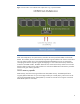
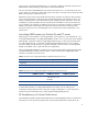
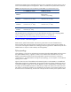
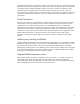
Figure 3: The charts compare DDR2 and DDR3 address and command signal topologies.
Memory Controller
Address / Command / Clock
Bus
Data Data
DDR2
Symmetrical T-Branch Topology
Memory Controller
Address / Command / Clock
Bus
Data Data
DDR3
Fly-by Topology
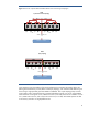
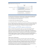
Fly-by topology solves the problem of the shrinking data-eye by eliminating the need to deliver the
data signals simultaneously to each DRAM. With Fly-by topology, each command and address signal
flows along a single path that goes from DRAM 0 to DRAM 8. This simpler topology helps increase
signal integrity. But it guarantees that the command and address signals won’t arrive at each DRAM
at the same time. If the signals arrive at DRAM 0 at time N, then they should arrive at DRAM 1 at time
N+1, DRAM 2 at time N+2, and so forth. The result is that, on a read, each DRAM presents its data
to the memory controller at a slightly different time.