TL881 MiniLibrary Drive Upgrade Procedure First Edition (May 1999) Part Number ER-TL881-DA.
Notice The information in this publication is subject to change without notice. COMPAQ COMPUTER CORPORATION SHALL NOT BE LIABLE FOR TECHNICAL OR EDITORIAL ERRORS OR OMISSIONS CONTAINED HEREIN, NOR FOR INCIDENTAL OR CONSEQUENTIAL DAMAGES RESULTING FROM THE FURNISHING, PERFORMANCE, OR USE OF THIS MATERIAL.
Contents About This Guide Text Conventions.................................................................................................... v Symbols in Text.....................................................................................................vi Symbols on Equipment ..........................................................................................vi Rack Stability .......................................................................................................
iv TL881 MiniLibrary Drive Upgrade Procedure List of Figures Figure 1. Figure 2. Figure 3. Figure 4. Parts Location ......................................................................................... 1 Removing the Skin Cover........................................................................ 3 Removing the Cover Plate ....................................................................... 5 Drive Caddy Assembly Parts ...................................................................
About This Guide This guide is designed to be used as step-by-step instructions for installation and as a reference for operation, troubleshooting, and future upgrades. Text Conventions This document uses the following conventions to distinguish elements of text: Keys Keys appear in boldface. A plus sign (+) between two keys indicates that they should be pressed simultaneously. USER INPUT User input appears in a different typeface and in uppercase. FILENAMES File names appear in uppercase italics.
vi TL881 MiniLibrary Drive Upgrade Procedure Symbols in Text These symbols may be found in the text of this guide. They have the following meanings. WARNING: Text set off in this manner indicates that failure to follow directions in the warning could result in bodily harm or loss of life. CAUTION: Text set off in this manner indicates that failure to follow directions could result in damage to equipment or loss of information.
About This Guide vii Power Supplies or Systems marked with these symbols indicate the equipment is supplied by multiple sources of power. WARNING: To reduce the risk of injury from electrical shock, remove all power cords to completely disconnect power from the system. Rack Stability WARNING: To reduce the risk of personal injury or damage to the equipment, be sure that: ■ The leveling jacks are extended to the floor. ■ The full weight of the rack rests on the leveling jacks.
viii TL881 MiniLibrary Drive Upgrade Procedure listed on the Compaq website. Access the Compaq website by logging on to the Internet at http://www.compaq.com.
About This Guide ix Compaq Authorized Reseller For the name of your nearest Compaq Authorized Reseller: ■ In the United States, call 1-800-345-1518. ■ In Canada, call 1-800-263-5868. ■ Elsewhere, see the Compaq website for locations and telephone numbers.
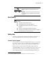
Adding a Second Tape Drive IMPORTANT: All screws that do not use lock washers, captive washers or lock nuts must have Loctite 222 applied when parts are reassembled in the field. If you ignore this step, you might cause premature failure of the mechanism. Parts Location Figure 1 shows the location of most of the field replaceable parts. Table 1 describes the parts. 5 3 6 4 2 1 7 8 9 14 13 12 11 Figure 1.
2 TL881 MiniLibrary Drive Upgrade Procedure Table 1 Parts Location Number Part (1) Magazine door (2) Door opener/Magazine lock (3) Shuttle cable (4) Shuttle (5) Shuttle motor (6) Drive caddy assembly (7) Fan (8) Power supply (9) Controller PWB (10) AC power switch (11) Control panel (12) Unlock/open switch (13) Magazine security lock (14) Leadscrew Overall Procedure NOTE: If the base module is part of an expanded TL881 MiniLibrary subsystem, refer to the TL881 Mini Library Ser
Adding a Second Tape Drive 3 4. Install the new drive using the procedure described in this document. 5. Replace the drive caddy assembly. 6. Replace the cover plate. 7. Replace the skin cover. Removing and Replacing the Skin Cover (Desktop Models Only) The skin cover is held in place by two screws on each side of the base module (Figure 2). SHR-1433 Figure 2. Removing the Skin Cover Removing Do these steps to remove the skin cover from the base module. 1.
4 TL881 MiniLibrary Drive Upgrade Procedure 1. Position the skin cover over the base module with the two angled surfaces facing toward the front. 2. Slide the skin cover over the module until it touches the front panel. 3. Insert the two screws on each side through the skin cover into the base module; insert and start all four screws before you tighten any of them. Removing and Replacing the Cover Plate Removing Do these steps to remove the cover plate from the base module. 1.
Adding a Second Tape Drive 5 SHR-120366 Figure 3. Removing the Cover Plate Removing and Replacing the Drive Caddy Assembly The drive caddy assembly is an enclosure that holds one or two DLT drives and the interconnecting cables. The assembly includes the SCSI interface connectors and cables for the base module, the power cables for the drives, and communication cables from the drives to the controller PWB. Removing Do these steps to remove the drive caddy assembly from the base module. 1.
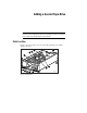
6 TL881 MiniLibrary Drive Upgrade Procedure 5 2 7 1 7 5 3 6 4 4 SHR-1204 Figure 4. Drive Caddy Assembly Parts 3. Disconnect the drive power “Y” cable (2) from the power supply connector. 4. Disconnect the drive 1 RS-422 cable (3) at the controller PWB end. 5. Remove two M4 x 8mm flat-head screws (4) along the upper edge of the drive caddy assembly. 6. Remove two M4 extension screws (5) at the top of the drive caddy assembly.
Adding a Second Tape Drive 7 7. Grasp the handle on top and lift the drive caddy assembly out of the base module carefully; be careful the door levers don’t bump against the chassis crossbrace. 8. Set the drive caddy assembly on the work surface and install the second tape drive as described in Installing the Second Tape Drive. Replacing Do these steps to replace the drive caddy assembly in the base module.
8 TL881 MiniLibrary Drive Upgrade Procedure Installing the Second Tape Drive Do the following steps to install the second tape drive. 1. Remove the four 6-32 sems pan-head Phillips screws (7) that hold the blank panel in place in the drive caddy assembly; there are two on the top of the assembly (Figure 4) and two on the bottom of the assembly. 2. Slide the blank panel out of the drive caddy assembly. 3.
Index B base module 2 C Compaq website viii Compq authorized resellers, telephone numbers viii technical support telephone numbers vii http://www.compaq.
2 TL881 MiniLibrary Drive Upgrade Procedure S SCSI cable connectors 5 second tape drive 7 skin cover 2 symbols in text vi symbols on equipment vi T Table 1 Parts Location 2 technical support viii telephone numbers viii text conventions v W warnings electrical shock vii rack stability vii www.compaq.com.