Hardware Reference Guide HP Compaq t5135/t5530 Thin Clients
© Copyright 2006, 2007 Hewlett-Packard Development Company, L.P. The information contained herein is subject to change without notice. Microsoft and Windows are trademarks of Microsoft Corporation in the U.S. and other countries. The only warranties for HP products and services are set forth in the express warranty statements accompanying such products and services. Nothing herein should be construed as constituting an additional warranty.
About This Book WARNING! Text set off in this manner indicates that failure to follow directions could result in bodily harm or loss of life. CAUTION: Text set off in this manner indicates that failure to follow directions could result in damage to equipment or loss of information. NOTE: ENWW Text set off in this manner provides important supplemental information.
iv About This Book ENWW
Table of contents 1 Product features Standard features ................................................................................................................................. 1 Front panel components ....................................................................................................................... 1 Secure USB compartment ports ........................................................................................................... 2 Rear panel components ...................
Grounding methods ............................................................................................................................ 23 8 Shipping information Shipping preparation .......................................................................................................................... 24 Important service repair information ...................................................................................................
1 Product features Standard features Thank you for purchasing an HP Compaq thin client. We hope you have years of use from our t5135 or t5530 thin clients. Our goal is to provide you with award-winning clients that are easy to deploy and manage with the power and reliability you expect. HP has partnered with Altiris to manage HP Compaq thin clients. Altiris Deployment Solution is a leadingedge tool to help with quick deployment and for ongoing management of the thin clients in your organization.
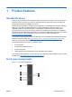
(1) Secure USB compartment (5) Line-out (headphone) audio connector (2) Power button (6) Line-in (microphone) connector (3) Flash activity LED (7) Universal serial bus (USB) connectors (2) (4) Power LED * For more information, refer to the model-specific QuickSpecs at http://h18004.www1.hp.com/products/quickspecs/ QuickSpecs_Archives/QuickSpecs_Archives.
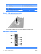
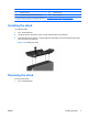
(2) Ethernet RJ-45 connector (6) Monitor connector (3) Parallel connector (7) Serial connector (4) Universal serial bus (USB) connectors (4) (8) Power connector For more information, see the model-specific QuickSpecs at http://h18004.www1.hp.com/products/quickspecs/ QuickSpecs_Archives/QuickSpecs_Archives.html Installing the stand To install the stand: 1. Turn unit upside down. 2. Locate the slots on the bottom of the unit into which the tabs on the stand fit. 3.
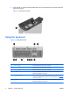
2. Press the tab (1), and then slide the stand about 1/2–inch toward the front of the unit and lift the stand off the unit (2). Figure 1-5 Removing the stand Using the keyboard Figure 1-6 Keyboard features 4 (1) Caps Lock key Activates/deactivates the Caps Lock feature. (2) Scroll Lock key Activates/deactivates the Scroll Lock feature. (3) Num Lock key Activates/deactivates the Num Lock feature.
(7) Application key1 Similar to the right mouse button, opens pop-up menus in a Microsoft Office application. May perform other functions in other software applications. (8) Editing keys Includes the following: Insert, Home, Page Up, Delete, End, and Page Down. Hold Ctrl and Alt while pressing Delete to restart the thin client. 1 Available in select geographic regions.
Serial number location Every thin client includes a unique serial number located as shown in the following illustration. Have this number available when contacting HP customer service for assistance.
2 Hardware changes General hardware installation sequence To ensure the proper installation thin client hardware components: 1. Back up any data, if necessary. 2. If the thin client is powered on: a. Turn the unit and any other attached devices off. b. Disconnect the power cord from the wall outlet. c. Disconnect any external devices or cables.
CAUTION: The ambient temperature inside of the secure USB compartment can reach up to 55°C in worst case conditions. Make sure the specifications for any device you install in the compartment indicate the device can tolerate a 55°C ambient environment. NOTE: In addition to following these instructions, follow the detailed instructions that accompany the accessory you are installing.
Installing the USB device ▲ Insert the USB device into the USB port in the secure USB compartment. See the following illustration for the location of the ports in the secure USB compartment. Figure 2-2 Secure USB compartment port location Replacing the secure USB compartment cover To replace the secure compartment cover: 1. Place the cover on top of the unit so it is offset about 1/2–inch toward the rear of the unit, allowing the tabs on the cover to align and insert into the slots on the chassis (1).
Replacing the battery Before beginning the replacement process, review General hardware installation sequence on page 7 for procedures you should follow before and after installing or replacing hardware. To replace the battery: 1. Remove the side access panel and metal side cover 2. Remove and replace the battery 3.
2. Lift the metal side cover up and off the unit (2). Figure 2-5 Removing the metal side cover Removing and replacing the battery To remove and replace the battery: 1. Locate the battery on the system board. 2. Pull back on the clip (1) that is holding the battery in place, and then remove the battery (2). Figure 2-6 Removing and replacing the internal battery 3. Insert the new battery and position the clip back into place.
2. Insert and tighten the three screws. Figure 2-7 Replacing the metal side cover To replace the access panel: 1. Place the access panel on the side of the unit, offset about 1/2–inch toward the front of the unit (1). 2. Slide the panel toward the rear of the unit until it locks into place (2). 3. Replace the two screws that secure the access panel to the chassis (3). Figure 2-8 Replacing the side access panel External drives Various external USB drives are available as options for the t5135/t5530.
3 Specifications Table 3-1 HP Compaq t5135/t5530 Thin Client Dimensions Width (front to back) 7.31 in. 18.57 cm Height (top to bottom) 7.31 in 18.57 cm Depth 2.06 in. 5.24 cm Approximate Weight 2.9 lb 1.3 kg 50° to 104° F 10° to 40° C -22° to 140° F -30° to 60° C Temperature Range (fanless design)* Operating** (max. rate of change is 10° C per hour or 18° F per hour) Nonoperating (max.
4 Security provisions Securing the thin client The HP Compaq t5135/t5530 thin client is designed to accept a security cable lock. This cable lock prevents unauthorized removal of the thin client, as well as locking the secure compartment. To order this option, visit the HP Web site at http://h30143.www3.hp.com/configure2.cfm. 1. Locate the cable lock slot on the back panel. 2. Insert the cable lock into the slot, and then use the key to lock it.
5 Mounting the thin client HP Quick Release The HP Compaq t5135/t5530 thin client incorporates four mounting points on each side of the unit. These mounting points follow the VESA (Video Electronics Standards Association) standard, which provides industry-standard mounting interfaces for Flat Displays (FDs), such as flat panel monitors, flat displays, and flat TVs. The HP Quick Release connects to the VESA-standard mounting points, allowing you to mount the thin client in a variety of orientations.
To use the HP Quick Release with a VESA-configured thin client: 1. Using four 10 mm screws included in the mounting device kit, attach one side of the HP Quick Release to the thin client as shown in the following illustration. Figure 5-2 Connecting the HP Quick Release to the thin client 2. Using four screws included in the mounting device kit, attach the other side of the HP Quick Release to the device to which you will mount the thin client. Make sure the release lever points upward.
3. Slide the side of the mounting device attached to the thin client (1) over the other side of the mounting device (2) on the device on which you want to mount the thin client. An audible 'click' indicates a secure connection. Figure 5-4 Connecting the thin client NOTE: When attached, the HP Quick Release automatically locks in position. You only need to slide the lever to one side to remove the thin client.
Figure 5-6 Thin client mounted on back of monitor stand ● You can mount the thin client on a wall. Figure 5-7 Thin client mounted on wall ● 18 You can mount the thin client under a desk.
Figure 5-8 Thin client mounted under desk Non-supported mounting option CAUTION: Mounting a thin client in an non-supported manner could result in failure of the HP Quick Release and damage to the thin client and/or other equipment. Do not mount the thin client on a flat panel monitor stand, between the panel and the stand.
6 Thin client operation Routine thin client care Use the following information to properly care for your thin client: ● Never operate the thin client with the outside panel removed. ● Keep the thin client away from excessive moisture, direct sunlight, and extreme heat and cold. For information about the recommended temperature and humidity ranges for the thin client, see Specifications on page 13. ● Keep liquids away from the thin client and keyboard.
Figure 6-2 Horizontal orientation ● You can lay the thin client under a monitor stand with at least one inch of clearance. Figure 6-3 Under monitor stand Non-supported orientation HP does not support the following orientation for the thin client. CAUTION: Non-supported placement of thin clients could result in operation failure and/or damage to the devices. CAUTION: ENWW Thin clients require proper ventilation to maintain operating temperature.
Do not put thin clients in drawers or other sealed enclosures. Thin clients require proper ventilation to maintain operating temperatures.
7 Electrostatic discharge A discharge of static electricity from a finger or other conductor may damage system boards or other static-sensitive devices. This type of damage may reduce the life expectancy of the device. Preventing electrostatic damage To prevent electrostatic damage, observe the following precautions: ● Avoid hand contact by transporting and storing products in static-safe containers. ● Keep electrostatic-sensitive parts in their containers until they arrive at static-free workstations.
8 Shipping information Shipping preparation Follow these suggestions when preparing to ship the thin client: 1. Turn off the thin client and external devices. 2. Disconnect the power cord from the electrical outlet, then from the thin client. 3. Disconnect the system components and external devices from their power sources, then from the thin client. 4.