HP 14 Notebook PC HP 14 TouchSmart Notebook PC Compaq 14 Notebook PC Compaq 14 TouchSmart Notebook PC HP 240 G2 Notebook PC HP 245 G2 Notebook PC Maintenance and Service Guide
© Copyright 2013 Hewlett-Packard Development Company, L.P. AMD and Radeon are trademarks of Advanced Micro Devices, Inc. Bluetooth is a trademark owned by its proprietor and used by HewlettPackard Company under license. Intel, Celeron, Core, and Pentium are trademarks of Intel Corporation in the U.S. and other countries.Microsoft and Windows are U.S. registered trademarks of the Microsoft group of companies. SD Logo is a trademark of its proprietor.
Safety warning notice WARNING! To reduce the possibility of heat-related injuries or of overheating the device, do not place the device directly on your lap or obstruct the device air vents. Use the device only on a hard, flat surface. Do not allow another hard surface, such as an adjoining optional printer, or a soft surface, such as pillows or rugs or clothing, to block airflow. Also, do not allow the AC adapter to contact the skin or a soft surface, such as pillows or rugs or clothing, during operation.
iv Safety warning notice
Table of contents 1 Product description ....................................................................................................................................... 1 Intel HM76 Express Chipset models ...................................................................................................................... 1 Intel Bay Trail chipset models ............................................................................................................................... 4 AMD models .......
Electrostatic discharge damage ..................................................................................... 40 Packaging and transporting guidelines ....................................................... 41 Component replacement procedures ................................................................................................................. 43 Battery .........................................................................................................................................
Computer Setup (BIOS) and Advanced System Diagnostics in SUSE Linux ........................................................ 101 Starting Computer Setup .................................................................................................................................. 101 Using Computer Setup ....................................................................................................................................... 101 Navigating and selecting in Computer Setup ..................
Restoring specific files .................................................................................................................... 114 Restoring specific files using Windows Backup and Restore ...................................... 114 Recovering the original system using HP Recovery Manager ........................................................ 114 What you need to know ................................................................................................
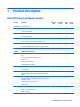
1 Product description Intel HM76 Express Chipset models Category Description Non-touch ; UMA Non-touch; discrete Touch; UMA Touch; discrete Product name HP 14 Notebook PC √ √ √ √ HP 14 TouchSmart Notebook PC √ √ √ √ Compaq 14 Notebook PC √ √ √ √ Compaq 14 TouchSmart Notebook PC √ √ √ √ HP 240 G2 Notebook PC √ √ √ √ Intel i5-3230M processor (2.6-GHz, 3-MB cache, 35 W) √ √ √ √ Intel i3-3110M processor (2.
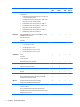
Category Description Non-touch ; UMA Non-touch; discrete Touch; UMA Touch; discrete √ √ √ √ √ √ √ √ √ √ √ √ √ √ √ √ DVD+/-RW Double-Layer SuperMulti √ √ √ √ Supports zero power optical drive √ √ √ √ Supports no optical drive option √ √ Single digital microphone √ √ √ √ HD audio √ √ √ √ Dual speakers √ √ √ √ HP TrueVision HD webcam (fixed, no tilt with activity LED, 1280×720 by 30 frames per second) √ √ √ √ Integrated 10/100 network interface card (NIC)
Category External media card Description Non-touch ; UMA Non-touch; discrete Touch; UMA Touch; discrete √ √ √ √ AC Smart Pin adapter plug √ √ √ √ Headphone/microphone in combo jack √ √ √ √ HDMI version 1.4 supporting 1920 ×1200 @ 60Hz √ √ √ √ RJ-45 (Ethernet, includes link and activity lights) √ √ √ √ USB 3.0 (1 port) √ √ √ √ USB 2.
Category Description Security Kensington Security Lock Non-touch ; UMA Non-touch; discrete Touch; UMA Touch; discrete √ √ √ √ √ √ √ √ Support Intel Anti-Theft Support Intel IPT OTP support Operating system Serviceability Preinstalled: ● Windows 8.1 ● Windows 8.1 downgrade to Windows 7 Professional (HP 240 models) ● Ubuntu √ √ ● FreeDOS 2.
Category Description Non-touch; UMA Touchscreen, 35.6-cm (14.
Category Description Non-touch; UMA Touch; UMA Wireless Integrated wireless local area network (WLAN) options by way of wireless module √ √ √ √ √ √ AC Smart Pin adapter plug √ √ Headphone/microphone in combo jack √ √ HDMI version 1.4 supporting 1920 ×1200 @ 60Hz √ √ RJ-45 (Ethernet, includes link and activity lights) √ √ USB 3.0 (1 port) √ √ USB 2.
Category Description Non-touch; UMA Touch; UMA √ √ OTP support Operating system Serviceability Preinstalled: ● Windows 8.
Category Description Non-touch; UMA Non-touch; discrete Touch; UMA Touch; discrete UMA graphics: Panel AMD Radeon™ HD 8400 Graphics (A6-5200) √ √ AMD Radeon HD 8330 Graphics (A4-5000) √ √ AMD Radeon HD 8280 Graphics (E2-3800) √ √ AMD Radeon HD 8210 Graphics (E1-2100) √ √ 35.6-cm (14.0-in), high-definition (HD), light-emitting diode (LED), SVA BrightView (1366×768) display; typical brightness: 200 nits √ √ Touchscreen, 35.6-cm (14.
Category Ethernet Description Non-touch; UMA Non-touch; discrete Touch; UMA Touch; discrete HD audio √ √ √ √ Dual speakers √ √ √ √ HP TrueVision HD webcam (fixed, no tilt with activity LED, 1280×720 by 30 frames per second) √ √ √ √ Integrated 10/100 network interface card (NIC) √ √ √ √ √ √ √ √ √ √ √ √ √ √ √ √ AC Smart Pin adapter plug √ √ √ √ Headphone/microphone in combo jack √ √ √ √ HDMI version 1.
Category Description Power requirements 65-W Smart AC adapter; for use in all countries except China and India) Non-touch; UMA Non-touch; discrete Touch; UMA √ √ Touch; discrete √ 65-W EM Smart AC adapter; for use in China and India only) √ √ √ 45-W Smart AC adapter; for use in all countries except China and India) √ 1 meter power cord √ √ √ √ 4-cell, 41-Whr Li-ion battery √ √ √ √ √ √ √ √ √ √ √ √ √ 3-cell, 31-Whr Li-ion battery Security Kensington Security Lock Support Int
2 External component identification Right side Component (1) Description Power light ● On: The computer is on. ● Blinking: The computer is in the Sleep state, a power-saving state. The computer shuts off power to the display and other unneeded components. ● Off: The computer is off or in Hibernation. Hibernation is a power-saving state that uses the least amount of power. NOTE: For select models, the Intel® Rapid Start Technology feature is enabled at the factory.
Left side Component (1) Description Security cable slot Attaches an optional security cable to the computer. NOTE: The security cable is designed to act as a deterrent, but it may not prevent the computer from being mishandled or stolen. (2) Power connector Connects an AC adapter. (3) AC adapter light ● On: The AC adapter is connected and the battery is charged. ● Amber: The AC adapter is connected and the battery is charging. ● Off: The computer is using battery power.
Component Description NOTE: When a device is connected to the jack, the computer speakers are disabled. NOTE: Be sure that the device cable has a 4-conductor connector that supports both audio-out (headphone) and audioin (microphone). Front Component Description Memory card reader Reads optional memory cards that store, manage, share, or access information.
Display Component Description (1) WLAN antennas (2)* Send and receive wireless signals to communicate with wireless local area networks (WLANs). (2) WWAN antennas (2)* (select models only) Send and receive wireless signals to communicate with wireless wide area networks (WWAN). (3) Webcam light On: The webcam is in use. (4) Webcam Records video and captures photographs. Some models allow you to video conference and chat online using streaming video.
Top TouchPad Component (1) Description TouchPad zone Moves the on-screen pointer and selects or activates items on the screen. NOTE: The TouchPad also supports edge-swipe gestures. (2) Left TouchPad button Functions like the left button on an external mouse. (3) Right TouchPad button Functions like the right button on an external mouse.
Lights Component Description (1) Caps lock light On: Caps lock is on, which switches the keys to all capital letters. (2) Mute light ● Amber: Computer sound is off. ● Off: Computer sound is on. (3) Wireless light On: An integrated wireless device, such as a wireless local area network (WLAN) device and/or a Bluetooth® device, is on. NOTE: On some models, the wireless light is amber when all wireless devices are off.
Button Component Description Power button ● When the computer is off, press the button to turn on the computer. ● When the computer is on, press the button briefly to initiate Sleep. ● When the computer is in the Sleep state, press the button briefly to exit Sleep. ● When the computer is in Hibernation, press the button briefly to exit Hibernation. CAUTION: Pressing and holding down the power button will result in the loss of unsaved information.
Keys Component Description (1) esc key Displays system information when pressed in combination with the fn key. (2) fn key Executes frequently used system functions when pressed in combination with the spacebaror the esc key. (3) Windows key Windows 8: Returns you to the Start screen from an open app or the Windows desktop. NOTE: Pressing the Windows key again will return you to the previous screen. Windows 7: Displays the Windows Start menu.
Bottom Component Description (1) Battery lock and unlock latch Locks and unlocks the battery in the battery bay. (2) Battery bay Holds the battery. (3) Vents (5) Enable airflow to cool internal components. NOTE: The computer fan starts up automatically to cool internal components and prevent overheating. It is normal for the internal fan to cycle on and off during routine operation. (4) Battery release latch Releases the battery. (5) Speaker openings (2) Produce sound.
Component Description CAUTION: To prevent an unresponsive system, replace the wireless module only with a wireless module authorized for use in the computer by the governmental agency that regulates wireless devices in your country or region. If you replace the module and then receive a warning message, remove the module to restore computer functionality, and then contact support through Help and Support. In Windows 78, from the Start screen, type help, and then select Help and Support.
Labels The labels affixed to the computer provide information you may need when you troubleshoot system problems or travel internationally with the computer. IMPORTANT: All labels described in this section will be located in one of 3 places depending on your computer model: Affixed to the bottom of the computer, located in the battery bay, or under the service door. ● Service label—Provides important information to identify your computer.
Component 22 (1) Serial number (2) Product number (3) Warranty period (4) Model number (select models only) (5) Revision number ● Regulatory label(s)—Provide(s) regulatory information about the computer. ● Wireless certification label(s)—Provide(s) information about optional wireless devices and the approval markings for the countries or regions in which the devices have been approved for use.
3 Illustrated parts catalog Computer major components Computer major components 23
Item Component (1) Display assembly (35.6-cm [14.0-in] HD, anti-glare, touchscreen) NOTE: Spare part number For display assembly spare part information, see Display assembly subcomponents on page 28.
Item Component Spare part number ● 747285-161 For use in Latin America For use in gray HP 14 or Compaq 14 models: ● For use in the United States 749781-001 ● For use in Latin America 749781-161 For use in gray HP 14 models: ● For use in Thailand 749781-281 ● For use in Taiwan 749781-AB1 ● For use in South Korea 749781-AD1 For use in black HP 240 and HP 245 models: ● For use in South Korea 749036-AD1 ● For use in Taiwan 749036-AB1 ● For use in Thailand 749036-281 ● For use in t
Item Component Spare part number ● UMA graphics, Intel HM86 chipset, Windows 8 Professional 747260-601 ● Discrete graphics, Intel HM86 chipset, without Windows 8 747261-001 ● Discrete graphics, Intel HM86 chipset, Windows 8 Standard 747261-501 ● Discrete graphics, Intel HM86 chipset, Windows 8 Professional 747261-601 ● UMA graphics, Intel HM76 chipset, without Windows 8 747262-001 ● UMA graphics, Intel HM76 chipset, Windows 8 Standard 747262-501 ● UMA graphics, Intel HM76 chipset, Wind
Item Component Spare part number For use only in models with an AMD E1-2100 processor and discrete graphics: ● Without Windows 8 747272-001 ● Windows 8 Standard 747272-501 (10) Optical drive connector 747244-001 (11) RTC battery 747132-001 (12) Memory module (PC3L, 12800, 1600-MHz): (13) 8-GB 693374-001 4 GB 691740-001 2 GB 691739-001 Processor (includes replacement thermal materials): Separate processors only available for models with Intel processors.
Item (21) Component Spare part number Atheros AR9485 802.11b/g/n WiFi Adapter for use in Brazil 712639-201 Realtek RTL8188EE 802.11bgn Wi-Fi Adapter 709848-001 Plastics Kit, includes: 747255-001 Service door 747255-001 NOTE: Included in the Plastics Kit.
Item Component Spare part number For use with HP 240 and HP 245 models 749551-001 (2) Webcam/microphone module 747144-001 (3) Raw display panel (35.6-cm [14.
Plastics Kit Item Component Spare part number Plastics Kit, includes: 747255-001 (1) Service door (2) Optical drive cover (for use in models without an optical drive) Rubber Kit Component Spare part number Rubber Kit for use in HP 14 and Compaq 14 models 747256-001 Rubber Kit for use in HP 240 models 749021-001 Rubber Kit for use in HP 245 models 753184-001 Display rubber pieces for back, front, and side Mylar display screw covers Rubber feet Keyboard aluminum foil pieces (4) Tape, control
Cable Kit Item Component Spare part number Cable Kit, includes: 750337-001 (1) Power button board cable (2) Card reader cable (3) USB cable (4) Power connector cable (5) Optical drive cable Cable Kit 31
Miscellaneous parts Component Spare part number HP Smart AC adapter: For use with computer models equipped with discrete graphics: ● 90-W PFC HP Smart AC adapter (for use in all countries except China and India) 710413-001 ● 90-W PFC EM HP Smart AC adapter (for use in China and India only) 710414-001 For use with computer models equipped with UMA graphics: ● 65-W non-PFC HP Smart AC adapter (for use in all countries except China and India) 710412-001 ● 65-W non-PFC EM HP Smart AC adapter (for us
Sequential part number listing Spare part number Description 490371-001 Power cord for use in North America (3-pin, black, 1.83-m) 490371-011 Power cord for use in Australia (3-pin, black, 1.83-m) 490371-021 Power cord for use in Europe, the Middle East, and Africa (3-pin, black, 1.83-m) 490371-031 Power cord for use in the United Kingdom and Singapore (3-pin, black, 1.83-m) 490371-061 Power cord for use in Italy (3-pin, black, 1.83-m) 490371-201 Power cord for use in Thailand (3-pin, black, 1.
34 Spare part number Description 712639-201 Atheros AR9485 802.11b/g/n WiFi Adapter for use in Brazil 713162-001 Intel Celeron 1000M, 1.8-GHz processor (2.0-MB L3 cache, dual core, 35 W) 714657-001 65-W non-PFC EM HP Smart AC adapter (for use in China and India only) 733476-001 Atheros AR9565 802.11bgn 1x1 WiFi + BT4.0 combo Adapter 737327-001 Intel Core i3 4000M, 2.40-GHz processor (3.0-MB L3 cache, dual core, 37 W) 740715-001 4-cell, 41-Whr, 2.
Spare part number Description 747250-001 DVD+/-RW Double-Layer SuperMulti Drive 747251-001 Power button board (includes cable) 747252-001 USB board (includes cable) 747253-001 TouchPad button board (includes cable) 747254-001 Card reader board (includes cable) 747255-001 Plastics Kit (includes service door and optical drive cover (for use in models without an optical drive) 747256-001 Rubber Kit for use in HP 14 and Compaq 14 models 747257-001 Raw display panel for use in HP 14 and Compaq 1
36 Spare part number Description 747265-501 System board for use only in models with UMA graphics, Celeron N2810 processor, and Windows 8 Standard (includes replacement thermal materials) 747265-601 System board for use only in models with UMA graphics, Celeron N2810 processor, and Windows 8 Professional (includes replacement thermal materials) 747266-001 Fan/heat sink assembly for use only with computer models equipped with an AMD processor and UMA graphics (includes replacement thermal materials)
Spare part number Description 747284-281 Top cover with keyboard for use in red HP 14 models in Thailand 747284-AB1 Top cover with keyboard for use in red HP 14 models in Taiwan 747284-AD1 Top cover with keyboard for use in red HP 14 models in South Korea 747285-001 Top cover with keyboard for use in gray Compaq 14 models in the United States 747285-161 Top cover with keyboard for use in gray Compaq 14 models in Latin America 749021-001 Rubber Kit for use in HP 240 models 749034-001 Display e
38 Spare part number Description 752884-601 System board for use only in models with UMA graphics, Celeron N2820 processor, and Windows 8 Professional (includes replacement thermal materials) 752897-001 System board for use only with computer models without Windows 8 and equipped with an AMD A6-5200 processor and UMA graphics (includes replacement thermal materials) 752897-501 System board for use only with computer models with Windows 8 Standard and equipped with an AMD A6-5200 processor and UMA gr
4 Removal and replacement procedures Preliminary replacement requirements Tools required You will need the following tools to complete the removal and replacement procedures: ● Flat-bladed screwdriver ● Magnetic screwdriver ● Phillips P0 and P1 screwdrivers Service considerations The following sections include some of the considerations that you must keep in mind during disassembly and assembly procedures.
Drive handling CAUTION: Drives are fragile components that must be handled with care. To prevent damage to the computer, damage to a drive, or loss of information, observe these precautions: Before removing or inserting a hard drive, shut down the computer. If you are unsure whether the computer is off or in Hibernation, turn the computer on, and then shut it down through the operating system. Before handling a drive, be sure that you are discharged of static electricity.
Typical electrostatic voltage levels Relative humidity Event 10% 40% 55% Walking across carpet 35,000 V 15,000 V 7,500 V Walking across vinyl floor 12,000 V 5,000 V 3,000 V Motions of bench worker 6,000 V 800 V 400 V Removing DIPS from plastic tube 2,000 V 700 V 400 V Removing DIPS from vinyl tray 11,500 V 4,000 V 2,000 V Removing DIPS from Styrofoam 14,500 V 5,000 V 3,500 V Removing bubble pack from PCB 26,500 V 20,000 V 7,000 V Packing PCBs in foam-lined box 21,000 V 11,0
● Avoid contact with pins, leads, or circuitry. ● Turn off power and input signals before inserting or removing connectors or test equipment. Equipment guidelines Grounding equipment must include either a wrist strap or a foot strap at a grounded workstation. ● When seated, wear a wrist strap connected to a grounded system. Wrist straps are flexible straps with a minimum of one megohm ±10% resistance in the ground cords. To provide proper ground, wear a strap snugly against the skin at all times.
Component replacement procedures This chapter provides removal and replacement procedures. Make special note of each screw's size and location during removal and replacement. Battery Description Spare part number 4-cell, 41-Whr, 2.8-Ah Li-ion battery 740715-001 3-cell, 31-Whr, 2.8-Ah Li-ion battery 746641-001 Before disassembling the computer, follow these steps: 1. Shut down the computer.
Display subcomponents (bezel, webcam, panel) This section describes removing display subcomponents that do not require that you remove the entire display assembly from the computer. You can remove the display bezel, webcam/microphone module, and display panel while the display assembly is still attached to the computer. To remove the remaining display subcomponents, you must remove the entire display assembly from the computer.
2. Remove the two Mylar screw covers (1) and the two Phillips PM2.5×4.5 screws (2) that secure the display bezel to the display assembly. 3. Flex the inside of the top edge (1), the left and right sides (2), and the bottom edge (3) of the display bezel until the bezel disengages from the display enclosure. 4. Remove the display bezel (4). 5. To remove the webcam/microphone module: a. Position the display assembly with the top edge toward you. b. Disconnect the cable (1) from the module.
c. 6. To remove the display panel: a. 46 Lift to disengage the adhesive that secures the webcam/microphone module to the display, and then remove the module (2). Remove the six Phillips PM2.5×4.0 screws (1) that secure the display panel to the enclosure, and then rotate the display panel and hinges forward to gain access to the hinge screws (2).
b. Remove the four Phillips PM2.0×3.0 screws (1) that secure the display panel to the hinges, and then rotate the display panel onto the keyboard (2).
c. On the back of the display panel, release the adhesive strip (1) that secures the display panel cable to the display panel, and then disconnect (2) and remove (3) the cable. Reverse this procedure to reassemble and install the display bezel, webcam/microphone module, and display panel.
Service door NOTE: The service door is available in the Plastics Kit. Description Spare part number Plastics Kit 747255-001 Before removing the service door, follow these steps: 1. Shut down the computer. If you are unsure whether the computer is off or in Hibernation, turn the computer on, and then shut it down through the operating system. 2. Disconnect all external devices connected to the computer. 3.
Optical drive Description Spare part number DVD+/-RW Double-Layer SuperMulti Drive 747250-001 Before removing the optical drive, follow these steps: 1. Shut down the computer. If you are unsure whether the computer is off or in Hibernation, turn the computer on, and then shut it down through the operating system. 2. Disconnect all external devices connected to the computer. 3.
6. Remove the optical drive bracket (2). Reverse this procedure to reassemble and install the optical drive.
WLAN module Description Spare part number Atheros AR9485 802.11b/g/n 1x1 WiFi Adapter 675794-001 Ralink RT3290LE 802.11bgn 1x1 Wi-Fi and Bluetooth 4.0 Combo Adapter 690020-001 Atheros AR9565 802.11bgn 1x1 WiFi + BT4.0 combo Adapter 733476-001 Atheros AR9485 802.11b/g/n WiFi Adapter for use in Brazil 712639-201 Realtek RTL8188EE 802.
3. Remove the WLAN module by pulling the module away from the slot at an angle (3). NOTE: If the WLAN antennas are not connected to the terminals on the WLAN module, the protective sleeves must be installed on the antenna connectors, as shown in the following illustration. Reverse this procedure to install the WLAN module.
Memory module Description Spare part number 8-GB (PC3L, 12800, 1600-MHz) 693374-001 4-GB (PC3L, 12800, 1600-MHz) 691740-001 2-GB (PC3L, 12800, 1600-MHz) 691739-001 Before removing a memory module, follow these steps: 1. Shut down the computer. If you are unsure whether the computer is off or in Hibernation, turn the computer on, and then shut it down through the operating system. 2. Disconnect all external devices connected to the computer. 3.
Top cover/keyboard NOTE: The top cover spare part kit includes the TouchPad.
Description Spare part number Top cover with keyboard for use in black HP 240 and HP 245 models: ● For use in the United States 749036-001 ● For use in Thailand 749036-281 ● For use in Taiwan 749036-AB1 ● For use in South Korea 749036-AD1 Top cover with keyboard for use in black HP 240 models: ● For use in Brazil 749036-201 ● For use in India 749036-D61 ● For use in Latin America 749036-161 Before removing the top cover/keyboard, follow these steps: 1. Shut down the computer.
2. Disconnect the following cables: (1): Power button board cable (2): Keyboard cable (3): Touchpad cable 3. Remove the 14 Phillips PM2.5×6.0 screws that secure the top cover to the computer. 4. Position the computer upright with the front toward you, and then open the computer. 5. Lift the rear edge of the top cover (1) until the left and right sides disengage from the base enclosure.
6. Remove the top cover (2). Reverse this procedure to install the top cover/keyboard. Note the antenna routing path on the bottom of the computer when reassembling the computer.
Power button board Description Spare part number Power button board (includes cable) 747251-001 Before removing the power button board, follow these steps: 1. Shut down the computer. If you are unsure whether the computer is off or in Hibernation, turn the computer on, and then shut it down through the operating system. 2. Disconnect all external devices connected to the computer. 3.
TouchPad button board Description Spare part number TouchPad button board (includes cable) 747253-001 Before removing the TouchPad button board, follow these steps: 1. Shut down the computer. If you are unsure whether the computer is off or in Hibernation, turn the computer on, and then shut it down through the operating system. 2. Disconnect all external devices connected to the computer. 3.
Display assembly This section describes removing the display assembly in its entirety and disassembling all the display subcomponents. If you only need to remove the display bezel, webcam/microphone module, or display panel, you do not need to remove the entire display assembly from the computer. See Display subcomponents (bezel, webcam, panel) on page 44 for more information about removing the display subcomponents that do not require that you remove the entire display assembly from the computer.
4. Remove the battery (see Battery on page 43). 5. Disconnect the WLAN module antenna cables from the WLAN module (see WLAN module on page 52). 6. Remove the following components: ● Service door (see Service door on page 49) ● Top cover (see Top cover/keyboard on page 55) To remove the display assembly: 1. Disengage the adhesive and disconnect the display panel cable (1) from the system board. 2. Remove the display panel cable from its routing path (2). 3.
5. Remove the display assembly (2). If it is necessary to replace any of the display assembly subcomponents: 1. To remove the display bezel: a. Remove the two Mylar screw covers (1) and the two Phillips PM2.5×4.5 screws (2) that secure the display bezel to the display assembly. The Mylar screw covers are included in the Rubber Kit, spare part number 747256-001 for HP 14 and Compaq 14 models, 749021-001 for HP 240 models, and 753184-001 for HP 245 models.
b. Flex the inside of the top edge (1), the left and right edges (2), and the bottom edge (3) of the display bezel until the bezel disengages from the display enclosure. c. Remove the display bezel (4). NOTE: In this procedure, the display will NOT be connected to the computer, as shown in the following image. 2. 64 To remove the webcam/microphone module: a. Position the display assembly with the top edge toward you. b. Disconnect the cable (1) from the module.
c. 3. Remove the webcam/microphone module (2). (The module is attached to the display enclosure with double-sided tape.) To remove the display panel: a. Remove the six Phillips PM2.5×4.0 screws (1) that secure the display panel to the enclosure, and then rotate the display panel (2) onto the computer. NOTE: In this procedure, the display will NOT be connected to the computer, as shown in the following image.
4. 66 b. On the back of the display panel, release the adhesive strip (1) that secures the display panel cable to the display panel, and then disconnect (2) and remove (3) the cable. c. Remove the panel from the display enclosure.
5. a. Remove the four Phillips PM2.0×3.0 screws (1) that secure the display hinges to the display panel. b. Remove the display hinges (2). To remove the wireless antenna cables and transceivers: a. Release the wireless antenna cables from the clips (1) built into the display enclosure. b. Remove the wireless antenna cables and transceivers (2).
6. To remove the display/webcam cable, release the webcam connector (1), webcam cable (2), and display cable (3) from the routing path built into the display enclosure. 7. If replacing the display enclosure, be sure that the other subcomponents (including the webcam/ microphone module, the antenna receivers, and all associated cables and hardware) are transferred to the new enclosure. Reverse this procedure to reassemble and install the display assembly.
USB board Description Spare part number USB board (includes cable) 747252-001 Before removing the USB board, follow these steps: 1. Shut down the computer. If you are unsure whether the computer is off or in Hibernation, turn the computer on, and then shut it down through the operating system. 2. Disconnect all external devices connected to the computer. 3.
Hard drive NOTE: The hard drive spare part kit does not include the hard drive cable or bracket. Description Spare part number 1-GB, 5400-rpm, 2.5-in 676521-005 750-GB, 5400-rpm, 2.5-in 634250-005 500-GB, 5400-rpm, 7.0-mm (for use only in HP 14 and Compaq 14 models) 683802-005 500-GB, 5400-rpm, 2.5-in (for use only in HP 240 models) 669299-005 320-GB, 5400-rpm, 2.5-in (for use only in HP 240 models) 622643-005 Hard drive bracket 747117-001 Before removing the hard drive, follow these steps: 1.
4. Disconnect the connector from the hard drive (4). 5. To remove the hard drive bracket, remove the four Phillips PM2.5×3.0 screws (1) that secure the bracket to the hard drive. 6. Remove the hard drive bracket from the hard drive (2). Reverse this procedure to reassemble and install the hard drive.
Optical drive connector Description Spare part number Optical drive connector 747244-001 Before removing the optical drive connector, follow these steps: 1. Shut down the computer. If you are unsure whether the computer is off or in Hibernation, turn the computer on, and then shut it down through the operating system. 2. Disconnect all external devices connected to the computer. 3.
System board NOTE: The system board spare part kit includes replacement thermal materials. NOTE: Intel models come with removable processors. AMD models come with processors soldered to the system board that cannot be removed or replaced.
Description Spare part number ● 747268-501 Windows 8 Standard System board for use only with models with an AMD E1-2100 processor and UMA graphics: ● Without Windows 8 747269-001 ● Windows 8 Standard 747269-501 System board for use only in models with an AMD A4-5000 processor and discrete graphics: ● Without Windows 8 747271-001 ● Windows 8 Standard 747271-501 System board for use only in models with an AMD E1-2100 processor and discrete graphics: ● Without Windows 8 747272-001 ● Window
2. Position the computer upright, and then disconnect the following cables from the system board: (2): Speaker cable (3): USB board cable (4): Optical drive connector cable 3. Remove the seven Phillips PM2.5×5.0 screws (1) that secure the system board to the base enclosure. 4. Lift the plastic tape from atop the fan (2).
5. Lift the side opposite of the connectors of the system board (3), and then pull the system board away from the connectors to remove it (4). Reverse this procedure to install the system board.
Fan/heat sink assembly NOTE: The fan/heat sink assembly spare part kit includes replacement thermal materials. Description Spare part number Models with Intel processors: ● UMA graphics and Intel HM76 chipset 747241-001 ● UMA graphics and an Intel Bay Trail chipset 747243-001 ● Discrete graphics and Intel HM76 chipset 747242-001 Models with AMD processors: ● UMA graphics 747266-001 ● Discrete graphics 747267-001 NOTE: To properly ventilate the computer, allow at least 7.6 cm (3.
a. Disconnect the fan cable (1) from the system board. b. Remove the fan from the clip on the system board (2). c. Remove the fan (3).
Remove the heat sink: a. Loosen the four Phillips screws that secure the heat sink to the system board (1). b. Remove the heat sink (2) from the system board.
AMD processor and UMA graphics The thermal material must be thoroughly cleaned from the surfaces of the heat sink and the system board components each time the heat sink is removed. Replacement thermal materials are included with the fan/ heat sink assembly, processor, and system board spare part kits.
● Thermal paste is used on the processor (1) and the heat sink section (2) that services it Intel processor and discrete graphics (not Bay Trail) Component replacement procedures 81
● Thermal paste is used on the processor (1) and the heat sink section (2) that services it ● Thermal paste is used on the graphics subsystem chip (3) and the heat sink section (4) that services it Intel processor and UMA graphics (not Bay Trail) ● Thermal paste is used on the processor (1) and the heat sink section (2) that services it AMD processor with discrete graphics 82 Chapter 4 Removal and replacement procedures
● Thermal paste is used on the processor (1) and the heat sink section (2) that services it AMD processor with UMA graphics ● Thermal paste is used on the processor (1) and the heat sink section (2) that services it Component replacement procedures 83
Reverse this procedure to reassemble and install the fan/heat sink assembly. Processor NOTE: This section applies only to computer models equipped with an Intel processor. AMD processors come soldered to the system board and cannot be removed or replaced. NOTE: The processor spare part kit includes replacement thermal materials. Description Spare part number Intel Core i5 3230M processor (2.60-GHz 3.0-MB L3 cache, dual core, 35 W) 711903-001 Intel Core i3 4000M processor (2.40-GHz, 3.
3. Lift the processor (3) straight up, and then remove it. NOTE: The gold triangle (4) on the processor must be aligned with the triangle icon embossed on the processor socket when you install the processor. Reverse this procedure to install the processor.
Power connector cable Description Spare part number Power connector cable 747116-001 Before removing the power connector cable, follow these steps: 1. Shut down the computer. If you are unsure whether the computer is off or in Hibernation, turn the computer on, and then shut it down through the operating system. 2. Disconnect all external devices connected to the computer. 3.
4. Remove the power connector cable (3). Reverse this procedure to install the power connector cable.
Card reader board Description Spare part number Card reader board (includes cable) 747254-001 Before removing the card reader board, follow these steps: 1. Shut down the computer. If you are unsure whether the computer is off or in Hibernation, turn the computer on, and then shut it down through the operating system. 2. Disconnect all external devices connected to the computer. 3.
Speakers Description Spare part number Speakers (includes left and right speakers and cable) 747259-001 Before removing the speakers, follow these steps: 1. Shut down the computer. If you are unsure whether the computer is off or in Hibernation, turn the computer on, and then shut it down through the operating system. 2. Disconnect all external devices connected to the computer. 3.
RTC battery Description Spare part number RTC battery 747132-001 Before removing the RTC battery, follow these steps: 1. Shut down the computer. If you are unsure whether the computer is off or in Hibernation, turn the computer on, and then shut it down through the operating system. 2. Disconnect all external devices connected to the computer. 3. Disconnect the power from the computer by first unplugging the power cord from the AC outlet and then unplugging the AC adapter from the computer. 4.
Hard drive connector Description Spare part number Hard drive connector 747240-001 Before removing the hard drive connector, follow these steps: 1. Shut down the computer. If you are unsure whether the computer is off or in Hibernation, turn the computer on, and then shut it down through the operating system. 2. Disconnect all external devices connected to the computer. 3.
Weight Before removing the weight, follow these steps: 1. Shut down the computer. If you are unsure whether the computer is off or in Hibernation, turn the computer on, and then shut it down through the operating system. 2. Disconnect all external devices connected to the computer. 3. Disconnect the power from the computer by first unplugging the power cord from the AC outlet and then unplugging the AC adapter from the computer. 4.
5 Using Setup Utility (BIOS) and HP PC Hardware Diagnostics (UEFI) in Windows 8 Setup Utility, or Basic Input/Output System (BIOS), controls communication between all the input and output devices on the system (such as disk drives, display, keyboard, mouse, and printer). Setup Utility (BIOS) includes settings for the types of devices installed, the startup sequence of the computer, and the amount of system and extended memory.
Downloading a BIOS update CAUTION: To reduce the risk of damage to the computer or an unsuccessful installation, download and install a BIOS update only when the computer is connected to reliable external power using the AC adapter. Do not download or install a BIOS update while the computer is running on battery power, docked in an optional docking device, or connected to an optional power source.
Using HP PC Hardware Diagnostics (UEFI) HP PC Hardware Diagnostics is a Unified Extensible Firmware Interface (UEFI) that allows you to run diagnostic tests to determine whether the computer hardware is functioning properly. The tool runs outside the operating system so that it can isolate hardware failures from issues that are caused by the operating system or other software components. To start HP PC Hardware Diagnostics UEFI: 1. Turn on or restart the computer, quickly press esc, and then press f2.
96 Chapter 5 Using Setup Utility (BIOS) and HP PC Hardware Diagnostics (UEFI) in Windows 8
6 Using Setup Utility (BIOS) and System Diagnostics in Windows 7 Setup Utility, or Basic Input/Output System (BIOS), controls communication between all the input and output devices on the system (such as disk drives, display, keyboard, mouse, and printer). Setup Utility (BIOS) includes settings for the types of devices installed, the startup sequence of the computer, and the amount of system and extended memory. Starting Setup Utility (BIOS) To start Setup Utility (BIOS), follow these steps: 1.
Downloading a BIOS update CAUTION: To reduce the risk of damage to the computer or an unsuccessful installation, download and install a BIOS update only when the computer is connected to reliable external power using the AC adapter. Do not download or install a BIOS update while the computer is running on battery power, docked in an optional docking device, or connected to an optional power source.
Using System Diagnostics System Diagnostics allows you to run diagnostic tests to determine if the computer hardware is functioning properly. To start System Diagnostics: 1. Turn on or restart the computer. While the “Press the ESC key for Startup Menu” message is displayed in the lower-left corner of the screen, press esc. When the Startup Menu is displayed, press f2. 2. Click the diagnostic test you want to run, and then follow the on-screen instructions.
100 Chapter 6 Using Setup Utility (BIOS) and System Diagnostics in Windows 7
7 Computer Setup (BIOS) and Advanced System Diagnostics in SUSE Linux Computer Setup, or Basic Input/Output System (BIOS), controls communication between all the input and output devices on the system (such as disk drives, display, keyboard, mouse, and printer). Computer Setup includes settings for the types of peripherals installed, the startup sequence of the computer, and the amount of system and extended memory. NOTE: Use extreme care when making changes in Computer Setup.
Use the tab key and the arrow keys to select File > Ignore Changes and Exit, and then press enter. – or – ● To save your changes and exit Computer Setup menus, click the Save icon in the lower-left corner of the screen, and then follow the on-screen instructions. – or – Use the tab key and the arrow keys to select File > Save Changes and Exit, and then press enter. Your changes go into effect when the computer restarts.
1. Start Computer Setup. 2. Use a pointing device or the arrow keys to select File > System Information. 3. To exit Computer Setup without saving your changes, click the Exit icon in the lower-left corner of the screen, and then follow the on-screen instructions. – or – Use the tab key and the arrow keys to select File > Ignore Changes and Exit, and then press enter.
● Hard disk test—This test analyzes the physical condition of the hard drive, and then checks all data in every sector of the hard drive. If the test detects a damaged sector, it attempts to move the data to a good sector. ● Memory test—This test analyzes the physical condition of the memory modules. If it reports an error, replace the memory modules immediately. ● Battery test—This test analyzes the condition of the battery and calibrates the battery if necessary.
8 Specifications Computer specifications Metric U.S. Depth 24.0 cm 9.5 in Width 34.6 cm 13.6 in Height 2.95 cm 1.16 in Weight 2.4 kg 5.29 lb Dimensions (touch models) Input power Operating voltage and current 18.5 V dc @ 3.5 A or 19.5 V dc @ 3.33 A – 65 W 19 V dc @ 4.74 A or 19.5 V dc @ 4.
Metric Brightness U.S. 200 nits (typical) Pixel resolution Pitch 0.197 × 0.197 mm Format 1366 × 768 Configuration RGB vertical stripe Backlight LED Character display 80 × 25 Total power consumption 2.0 W Viewing angle ±65° horizontal, ±50° vertical (typical) Hard drive specifications 1-TB* 750-GB* 500-GB* 320-GB* (9.5 mm) (7.0 mm) (9.5 mm) Dimensions Height 9.5 mm 9.5 mm 7.0 mm or 9.5 mm 7.0 mm or 9.5 mm Length 100.4 mm 100.4 mm 100.6 mm 100.4 mm Width 69.9 mm 69.
9 Backing up, restoring, and recovering in Windows 8 This chapter provides information about the following processes: ● Creating recovery media and backups ● Restoring and recovering your system Creating recovery media and backups 1. After you successfully set up the computer, create HP Recovery media. This step creates a backup of the HP Recovery partition on the computer.
● If your computer does not include an integrated optical drive with DVD writer capability, but you would like to create DVD recovery media, you can use an external optical drive (purchased separately) to create recovery discs, or you can obtain recovery discs for your computer from support. See the Worldwide Telephone Numbers booklet included with the computer. You can also find contact information from the HP website. Go to http://www.hp.
● If you have replaced the hard drive, you can use the Factory Reset option of HP Recovery media to restore the factory image to the replacement drive. For more information, see Recovering using HP Recovery Manager on page 109. ● If you wish to remove the recovery partition to reclaim hard drive space, HP Recovery Manager offers the Remove Recovery Partition option. For more information, see Removing the HP Recovery partition on page 110.
1. Press f11 while the computer boots. – or – Press and hold f11 as you press the power button. 2. Choose your keyboard layout. 3. Select Troubleshoot from the boot options menu. 4. Select Recovery Manager, and then follow the on-screen instructions. Using HP Recovery media to recover You can use HP Recovery media to recover the original system. This method can be used if your system does not have an HP Recovery partition or if the hard drive is not working properly. 1.
10 Backing up, restoring, and recovering in Windows 7 Your computer includes tools provided by the operating system and HP to help you safeguard your information and retrieve it if ever needed. Creating backups 1. Use HP Recovery Manager to create recovery media immediately after you set up the working computer. 2. As you add hardware and software programs, create system restore points. 3.
Creating the recovery media 1. Select Start and type recovery in the search field. Select Recovery Manager from the list. Allow the action to continue, if prompted. 2. Click Recovery Media Creation. 3. Follow the on-screen instructions to continue. To recover, see Recovering the original system using HP Recovery Manager on page 114. Creating system restore points A system restore point is a snapshot of certain hard drive contents saved by Windows System Restore at a specific time.
Tips for a successful backup ● Number backup discs before inserting them into the optical drive. ● Store personal files in the Documents, Music, Pictures, and Videos libraries, and back up these folders periodically. ● Save customized settings in a window, toolbar, or menu bar by taking a screen shot of your settings. The screen shot can be a time-saver if you have to re-enter your preferences. To create a screen shot: 1. Display the screen you want to save. 2.
Restore and recovery Restoring to a previous system restore point Sometimes installing a software program causes your computer or Windows to behave unpredictably. Usually uninstalling the software fixes the problems. If uninstalling does not fix the problems, you can restore the computer to a previous system restore point (created at an earlier date and time). To restore to a previous system restore point, when the computer was running correctly: 1.
● If the recovery media do not work, you can obtain recovery discs for your system from the HP website. ● The Minimized Image Recovery option is recommended for advanced users only. All hardware-related drivers and software are re-installed, but other software applications are not. Do not interrupt the process until it is complete, otherwise the recovery will fail.
1. Insert the flash drive into a USB port. 2. Restart the computer. 3. Press esc while the computer is restarting, and then press f9 for boot options. 4. Select the flash drive from the boot options window.
11 Backup and Recovery in SUSE Linux Recovery after a system failure is as good as your most recent backup. As you add new software and data files, you should continue to back up your system on a regular basis to maintain a reasonably current backup. Backing up your information You should back up your computer files on a regular schedule to maintain a current backup. You can manually back up your information to an optional external drive, a network drive, or discs.
CAUTION: Using Recovery completely erases hard drive contents and reformats the hard drive. All files you have created and any software installed on the computer are permanently removed. The recovery tool reinstalls the original operating system and HP programs and drivers that were installed at the factory. Software, drivers, and updates not installed by HP must be manually reinstalled. Personal files must be restored from a backup.
12 Power cord set requirements The wide-range input feature of the computer permits it to operate from any line voltage from 100 to 120 volts ac, or from 220 to 240 volts ac. The 3-conductor power cord set included with the computer meets the requirements for use in the country or region where the equipment is purchased. Power cord sets for use in other countries and regions must meet the requirements of the country or region where the computer is used.
Requirements for specific countries and regions Country/region Accredited agency Applicable note number Argentina IRAM 1 Australia SAA 1 Austria OVE 1 Belgium CEBEC 1 Brazil ABNT 1 Canada CSA 2 Chile IMQ 1 Denmark DEMKO 1 Finland FIMKO 1 France UTE 1 Germany VDE 1 India ISI 1 Israel SII 1 Italy IMQ 1 Japan JIS 3 The Netherlands KEMA 1 New Zealand SANZ 1 Norway NEMKO 1 The People's Republic of China CCC 4 Saudi Arabia SASO 7 Singapore PSB 1 So
Country/region Accredited agency Applicable note number 2. The flexible cord must be Type SVT/SJT or equivalent, No. 18 AWG, 3-conductor. The wall plug must be a two-pole grounding type with a NEMA 5-15P (15 A, 125 V ac) or NEMA 6-15P (15 A, 250 V ac) configuration. CSA or C-UL mark. UL file number must be on each element. 3. The appliance coupler, flexible cord, and wall plug must bear a “T” mark and registration number in accordance with the Japanese Dentori Law.
122 Chapter 12 Power cord set requirements
13 Statement of Volatility The purpose of this document is to provide general information regarding non-volatile memory in industrystandards based HP Business Notebook PC systems and provide general instructions for restoring nonvolatile memory that can contain personal data after the system has been powered off and the hard drive has been removed. HP Business Notebook PC products that use Intel®-based or AMD®-based system boards contain volatile DDR memory.
Then select Un-configure AMT on next boot. Select Save then Yes. Select the File menu, and then select Save Changes and Exit. Reboot the system and confirm that you want to un-configure AMT. 2. j. If the optional Intel® Anti-Theft Technology (AT) was activated, contact the provider to de-activate it. k. If the optional Absolute® Software Computrace® management and tracking service was activated on the notebook PC, contact the provider to deactivate it. l.
Non Volatile Memory Type Amount (Size) Does this memory store customer data? Does this memory retain data when power is removed? What is the purpose of this memory? How is data input into this memory? How is this memory write protected? Controller (NIC) EEPROM 64 Kbytes (not customer accessible) No Yes Store NIC configuration and NIC firmware. Using a utility from the NIC vendor that can be run from DOS. A utility is required to write data to this memory and is available from NIC vendor.
Non Volatile Memory Type Amount (Size) Does this memory store customer data? Does this memory retain data when power is removed? What is the purpose of this memory? How is data input into this memory? How is this memory write protected? 802.11 WLAN EEPROM 4kb to 8kb No Yes Stores configuration and calibration data. Programmed at the factory. Tools for writing data to this memory are not made public.
This relates to clearing the Real Time Clock (RTC) CMOS memory that contains PC configuration data. 6. Does resetting the CMOS configuration memory return the PC back to factory defaults? The process of resetting the CMOS will return certain system settings to factory default but will not reset many of the system data and configuration defaults to their factory settings.
128 Chapter 13 Statement of Volatility
14 Recycling Battery When a non-rechargeable or rechargeable battery has reached the end of its useful life, do not dispose of the battery in general household waste. Follow the local laws and regulations in your area for battery disposal. HP encourages customers to recycle used electronic hardware, HP original print cartridges, and rechargeable batteries. For more information about recycling programs, see the HP Web site at http://www.hp.com/ recycle. Display WARNING! The backlight contains mercury.
2. Lift up and out on the left and right inside edges (1) and the top and bottom inside edges (2) of the display bezel until the bezel disengages from the display assembly. 3. Remove the display bezel (3). 4. Disconnect all display panel cables (1) from the display inverter and remove the inverter (2). 5. Remove all screws (1) that secure the display panel assembly to the display enclosure.
6. Remove the display panel assembly (2) from the display enclosure. 7. Turn the display panel assembly upside down. 8. Remove all screws that secure the display panel frame to the display panel. 9. Use a sharp-edged tool to cut the tape (1) that secures the sides of the display panel to the display panel frame. 10. Remove the display panel frame (2) from the display panel. 11. Remove the screws (1) that secure the backlight cover to the display panel.
12. Lift the top edge of the backlight cover (2) and swing it outward. 13. Remove the backlight cover. 14. Turn the display panel upright. 15. Remove the backlight cables (1) from the clip (2) in the display panel. 16. Turn the display panel upside down.
17. Remove the backlight frame from the display panel. WARNING! The backlight contains mercury. Exercise caution when removing and handling the backlight to avoid damaging this component and causing exposure to the mercury. 18. Remove the backlight from the backlight frame. 19. Disconnect the display cable (1) from the LCD panel. 20. Remove the screws (2) that secure the LCD panel to the display rear panel. 21. Release the LCD panel (3) from the display rear panel.
22. Release the tape (4) that secures the LCD panel to the display rear panel. 23. Remove the LCD panel. 24. Recycle the LCD panel and backlight.
Index A AC adapter 12 AC adapter, spare part number 33 action keys identifying 18 antennas illustrated 29 removing 67, 68 spare part number 34 audio, product description 2, 5, 8 audio-out (headphone)/audio-in (microphone) jack 12 B backup 117 backups 107, 111 base enclosure illustrated 27 spare part number 34 battery illustrated 27 removing 43 spare part number 34 battery bay, identifying 19 battery lock and unlock latch, identifying 19 battery release latch 19 BIOS determining version 93, 97, 102 downloadi
removing 70 spare part number 33 specifications 106 Hard drive bracket illustrated 29 spare part number 34 hard drive bracket removing 71 hard drive connector illustrated 27 removing 91 hard drive light 11 HDMI port identifying 12 hinges illustrated 29 removing 46, 65, 66 spare part number 34 HP PC Hardware Diagnostics (UEFI) downloading 95 using 95 HP Recovery Manager 114 correcting boot problems 110 starting 109 HP Recovery media creating 107 recovery 110 HP Recovery partition recovery 109 removing 110 I
removing 84 spare part number 33 product description audio 2, 5, 8 chipset 1, 4, 7 display panel 1, 4, 8 Ethernet 2, 5, 9 external media cards 3, 6, 9 graphics 1, 4, 7 hard drive 2, 5, 8 keyboard 3, 6, 9 memory module 1, 5, 8 microphone 2, 5, 8 operating system 4, 7, 10 optical drive 2, 5, 8 pointing device 3, 6, 9 ports 3, 6, 9 power requirements 3, 6, 10 processor 1, 4, 7 product name 1, 4, 7 security 4, 6, 10 serviceability 4, 7, 10 video 2, 5, 8 wireless 2, 6, 9 product name 1, 4, 7 product name and num
removing 46, 65, 66 spare part number 34 webcam/microphone module illustrated 29 removing 45, 64 spare part number 34 weight removing 92 Windows File History 108 restoring files 108 system restore point 107 Windows Backup and Restore restoring files 114 Windows key, identifying 18 wireless antennas illustrated 29 removing 67, 68 spare part number 34 wireless certification label 22 wireless light 16 wireless, product description 2, 6, 9 WLAN antennas, identifying 14 WLAN device 22 WLAN label 22 WLAN module i