E nglish HP NetServer Storage System/6 User Guide HP Part Number D3604-90004 Printed in May 1996
Notice The information contained in this document is subject to change without notice. Hewlett-Packard makes no warranty of any kind with regard to this material, including, but not limited to, the implied warranties of merchantability and fitness for a particular purpose. Hewlett-Packard shall not be liable for errors contained herein or for incidental or consequential damages in connection with the furnishing, performance, or use of this material.
E nglish Contents 1 Introduction...................................................................................................1 Basic Installation............................................................................................2 Unpacking the NetServer Storage System/6 ..................................................3 Contents of the NetServer Storage System/6 Package ..............................3 Identifying Parts of the NetServer Storage System/6 .................................
Contents If the LED Readout Shows a Fan Fault (FF)............................................. 33 If the LED Readout Shows a Line Fault (LF) ............................................ 33 If the LED Readout Shows a Power Supply Fault (PF) ............................ 33 If the SCSI Devices Fail to Spin Up ......................................................... 33 If the Host Cannot Communicate With the Storage System ..................... 34 If the Hot-Swap Disk Power LEDs are Flashing .................
B Regulatory Information .............................................................................. 59 Notice for USA: FCC Statements ................................................................ 59 Class B Product Statement ...................................................................... 59 Country Notices ........................................................................................... 60 Notice for Canada: DOC Requirements ...................................................
E nglish 1 Introduction The NetServer Storage System/6 provides external mass storage for use with the current line of HP NetServers. The NetServer Storage System/6 is compatible with the Small Computer System Interface (SCSI-2) industry standard. Both Fast and Fast-Wide SCSI-2 are supported. The embedded SCSI controllers in NetServers, SCSI host bus adapters (HBA) or Disk Array Controllers (DAC) provide the SCSI interface between the host system and the storage system.
1 Introduction Basic Installation This section provides the basic information for installing the NetServer System/6. For detailed information, refer to the applicable chapter or section. Please also read the section “General Operating Instructions” in this chapter before installing the storage system. The basic steps for installing the storage system are as follows: 1. Unpack the device and inventory the accessories as described in the next section “Unpacking the NetServer Storage System/6.” 2.
1 Introduction E nglish 11. Configure the system with the appropriate drivers and/or operating system, as described in the user’s manual of the HP NetServer or disk array controller. Unpacking the NetServer Storage System/6 The instructions for unpacking your storage system are printed on the shipping carton. Keep all of the packing material, including the plastic bags, in case you need to repackage the storage system. When everything is unpacked, make sure you have all the items.
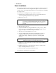
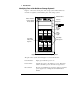
1 Introduction Identifying Parts of the NetServer Storage System/6 Figure 1-1 shows the various parts of the storage system. Please take a few moments to acquaint yourself with the parts of the storage system. LED Readout Power Indicator Power Switch Chassis Keylock Reset Switch Drive Activity Light Drive Power Light Hot-Swap Subsystem Hot-Swap Subsystem Keylock Figure 1-1.
LED Readout Displays “HP” (the default) or the unit identification number during normal operation, displays status information during a self-test or warns of an error condition. Chassis Keylock The front bezel is locked to the chassis with the key lock near the top of the bezel. When the bezel is in place, it effectively locks the chassis door. SCSI Device Shelves Standard SCSI devices, such as a DAT tape drive or an independent hard disk drive, can be installed in the SCSI device shelves.
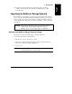
1 Introduction Chassis Fan Unused SCSI Connectors Knockouts Power Cord Connection Voltage Select Switch Power Supply Fan Figure 1-2. Rear View of the Storage System The parts of the system shown in Figure 1-2 are described below: 6 Chassis Fan Provides cooling for the storage system. SCSI Connectors Provides 68-pin, high-density SCSI interface connections to the storage system cabinet.
1 Introduction E nglish General Operating Instructions Please read the following instructions carefully. They contain information on how to avoid data loss and damage to the system due to improper handling. Reset Switch The front panel’s reset switch resets the power supply, performs a self test, and can be used to set the unit identification number. Power Supply Reset If the power supply shuts down, momentarily pressing the reset switch initiates a power supply reset.
1 Introduction 2. Release the reset switch when the desired number displays. The unit identification number displayed is stored in the EEPROM. The unit identification number does not change even if the storage system is powercycled (unless this procedure is repeated). NOTE The power supply does not reset when the unit identification number is changed. Power Cycling On an active network, switching the storage system power on or off while the host system is operating may affect server operation.
Temperature Control Keeping the unit within the range of normal operating temperatures (see Appendix A, “Specifications”) is important to the long life and proper function of the storage system. If the storage system cabinet has been exposed to temperature extremes, allow two hours for it to stabilize to room temperature and humidity before switching on the power. Blank filler panels that cover the SCSI device shelves and the disk module shelves are installed by the factory.
1 Introduction Hot-Swap Disk Module Care and Relocation Handle disk modules carefully. Disk modules are more susceptible to shock, vibration and electro-static discharge when they are not in the cabinet. Also, do not touch the SCSI edge connector pins when a disk module is out of the cabinet. The oils on your skin could weaken the contact. Once the storage system has been configured and installed, a disk module should not be moved from one hot-swap shelf to another shelf.
This chapter describes the NetServer Storage System/6, switch settings and common cabling configurations. Once the addresses are set and cabling is configured, the hardware can be installed as described in the next chapter. CAUTION Be careful when handling electronic components. Electronic components can be easily damaged by static electricity. Leave these sensitive components in their anti-static bags until you are ready to install them. Handle accessories as little as possible.
2 Cabling Storage Devices and Setting SCSI Addresses The basic procedure for configuring the storage system is as follows: 1. Determine the desired configuration. 2. Power down the storage system and detach all power cords and external cables. 3. Open the storage system door. The procedure is described in the “Opening the Door” section of this chapter. 4. Set the switches that determine the SCSI addresses for the hot-swap cages as described in the “Setting SCSI Addresses” section of this chapter. 5.
2 Cabling Storage Devices and Setting SCSI Addresses E nglish 4. Remove the front bezel. Pull the top of the bezel forward, swinging it down to clear the retaining clips at the bottom of the chassis. Lift the bezel away from the chassis, as shown in Figure 2-1. Figure 2-1. Removing the Bezel and Opening the Door 5. Loosen the door mounting screws using a straight-blade screwdriver. (The screws remain attached to the door.) 6. Swing the door open, as shown in Figure 2-1.
2 Cabling Storage Devices and Setting SCSI Addresses Setting SCSI Addresses The following is a description of the switch settings on the rear of the hot-swap subsystem cage (see Figure 2-1). The default switch setting is described in the “Cabling Configurations” section of this chapter. NOTE The numbers on the front bezel simply denote the position of the disk module in relation to the hot-swap subsystem. These numbers are not related to the SCSI addresses.
2 Cabling Storage Devices and Setting SCSI Addresses E nglish The switch setting location and functions are the same on both cages. The switch 6 setting differentiates the upper and lower cages. Table 2-1. Switch Functions and Settings Switch Functions Settings 1 Not Used Always set to Off. 2 Not Used Always set to Off. 3 High/Low Addresses On Fast-Wide (68 pin) SCSI Only. Sets the drives to the upper eight SCSI addresses. Off Sets the drives to the lower eight SCSI addresses.
2 Cabling Storage Devices and Setting SCSI Addresses Switches 3, 4 and 6 determine the SCSI address setting for each shelf in the hotswap subsystem. Table 2-2 describes the settings and the shelf’s SCSI address. Table 2-2.
external cables connect from the host system to the rear panel of the storage system cabinet. For instructions on connecting the external cables to the storage system, consult the host system user’s guide or in the case of a DAC card, the user’s guide for the DAC card. At least one external SCSI cable is required to attach each storage system to the host system. All connections from the storage system to the host must be direct.
2 Cabling Storage Devices and Setting SCSI Addresses System or Accessory Array Model SCSI Port high density. 1.0-Meter Cable Number C2960A* 2.5-Meter Cable Number NetServer LS Embedded Controller Fast-Wide SCSI-2 68-pin high density. C2911A (.9mts) D3636A NetServer LS Array Model Fast-Wide SCSI-2 68-pin ultra-high density. C3726A D3637A EISA DAC Fast SCSI-2 50-pin high density. 5181-7705 C2960A* D3635A PCI DAC Fast-Wide SCSI-2 68-pin ultra-high density.
2 Cabling Storage Devices and Setting SCSI Addresses E nglish Storage System Layout In the configuration drawings in this section, the SCSI device shelves and the hot-swap cages are mapped as shown in Figure 2-3. SCSI Device Shelf SCSI Device Shelf Hot-Swap Cage Hot-Swap Cage Figure 2-3. Storage System Map Only the internal HP cables shown in Table 2-4 are supported. Table 2-4.
2 Cabling Storage Devices and Setting SCSI Addresses Default Cabling Configuration (Non-Duplex) External terminator built into cable SCSI Device Shelf C11 68 to 50 pin adapter SCSI Device Shelf Internal terminator C14 C20 SCSI A SCSI B SCSI C SCSI D C20 Hot Swap Subsystem Figure 2-4.
2 Cabling Storage Devices and Setting SCSI Addresses E nglish Duplex Configuration External terminator built into cable SCSI Device Shelf C11 SCSI Device Shelf Internal terminator SCSI A SCSI B SCSI C SCSI D C20 C20 Hot Swap Subsystem Figure 2-5. Duplex Configuration In this example, the SCSI device shelves are connected to the upper hot-swap cage. Make sure the addresses in the SCSI device shelves are unique to each device, including the hot-swap disk modules.
2 Cabling Storage Devices and Setting SCSI Addresses Alternate Non-Duplex Configuration External terminator built into cable SCSI Device Shelf C11 SCSI Device Shelf C14 SCSI A SCSI B SCSI C SCSI D Hot Swap Subsystem C20 Figure 2-6. Alternate Non-Duplex Configuration In this example, eight devices are connected to one SCSI channel.
2 Cabling Storage Devices and Setting SCSI Addresses E nglish Alternate Duplex Configuration External terminator built into cable C11 SCSI Device Shelf SCSI Device Shelf 68 to 50 pin Adapter Internal Terminator C20 SCSI A SCSI B SCSI C SCSI D C20 Hot Swap Subsystem C20 Figure 2-7. Alternate Duplex Configuration The SCSI device shelves and each of the hot-swap cages are on separate SCSI channels.
E nglish 3 Installing Hardware Accessories This section describes how to physically install the SCSI mass storage devices in the storage system. There are two categories of mass storage devices—the hot-swap modules and the SCSI devices that can be installed in the SCSI device shelves. Installing Hot-Swap Storage Devices Only SCA-2 compliant, single-ended, Fast SCSI-2, hot-swap disk modules can be installed in the hot-swap subsystem.
3 Installing Hardware Accessories Installing a New Hot-Swap Disk Module This section describes the installation of a new hot-swap disk module. CAUTION Use one of the six (6) vertical shelves in the system. Do not attempt to install the hot-swap disk module in the SCSI device shelves. Complete the following procedure to install a new disk module: 1. Unlock the hot-swap disk module keylock and remove the filler panel in the disk shelf by pulling the filler panel straight out.
E nglish 3 Installing Hardware Accessories Figure 3-2. Installing the Hot-Swap Disk Module Removing a Hot-Swap Disk Module This section describes the process for removing a hot-swap disk module. CAUTION The module may be spinning and may be warm to touch. Complete the following procedure to remove a disk module: 1. Verify the hot-swap disk module keylock is unlocked, and unlock the hotswap disk module by pushing the locking tab down and lifting the front lever. 2.
3 Installing Hardware Accessories Figure 3-3. Removing the Hot-Swap Disk Module 3. Wait for the drive to stop spinning, then turn the hot-swap disk module slowly to its horizontal storage orientation. 4. Place the hot-swap disk module in an electrostatic protected container. Do not stack hot-swap disk modules. 5. Replace the blank filler panel or install a replacement disk module.
Installing a SCSI Device in a SCSI Device Shelf Almost any Fast SCSI-2 single-ended 3.5-inch or 5.25-inch device, such as a digital audio tape (DAT), CD-ROM or SCSI hard disk drive, can be installed in a SCSI device shelf. The details for configuring the device, such as jumper settings, are supplied by the manufacturer of the device. Internal cabling configurations are described in the “Cabling Configurations” section of this manual.
3 Installing Hardware Accessories NOTE Do not dispose of the blank filler panel. If you decide to operate the storage system with an empty bay, it must be covered with a blank filler panel to ensure proper cooling, and compliance with RFI and safety standards. 6. Mount the device in an HP tray if necessary. 7. Configure the device per manufacturer’s instructions. 8. Secure the drive and tray in the SCSI device shelf using the same screws used to attach the filler panel. 9.
E nglish 4 Troubleshooting If you are having problems installing or configuring the storage system, there are a number of tools and procedures available to help you resolve the problem. If you need assistance from HP, the “Service and Support” chapter of this manual contains information on service and support. WARNING Whenever opening the door, disconnect the power cords to avoid exposure to high energy levels, which may cause burns when parts are short-circuited by metal objects such as tools or jewelry.
4 Troubleshooting If The System Will Not Power On If, after pressing the power switch, you see: the power indicator LED fails to light, the LED readout fails to light, the chassis fan is not working, and the power supply fan is not working, the storage system has not powered up. Check the items listed below: • Verify the voltage switch on the power supply is in the correct position. • Ensure all cables and power cords are firmly plugged into the proper receptacles.
If the LED Readout Shows a Fan Fault (FF) If the system powers on, but the main chassis fan is not operating and/or “FF” is displayed, open the door and verify the fan cable is connected to the fan connector on the management board. (Refer to the cable management label on the inside of the door.) CAUTION Do not operate the storage system when the fan is not operating.
4 Troubleshooting If the Host Cannot Communicate With the Storage System If the SCSI devices spin up, but the host cannot access the SCSI devices, do the following on the storage system: • Verify all of the drive modules are inserted correctly and latched. (It may be necessary to remove and reinstall all hot-swap disk modules.) • Make sure the system is configured properly, including the devices installed in the SCSI device shelves.
4 Troubleshooting E nglish • Verify the network operating system supports the configuration. • Verify the same SCSI channel is not used for both internal and external SCSI devices. • Verify with the ECU utility that your SCSI controllers are properly configured. • Make sure the NOS and the appropriate drivers are properly installed for your SCSI and DAC controllers. (Refer to the related NOS, NetServer, HBA or DAC documentation for additional information.
4 Troubleshooting • Run the hot-swap temperature self test by powering up the storage system. The hot-swap assembly should briefly flash red. If it fails to flash, the storage system may require service. Error Messages The front panel of the storage system includes two-digit, seven-segment LEDs. When operations are normal, the display will show “HP” or the unit identification number. The LEDs are powered by the internal power supply, and when the power supply is not working there will be no display.
4 Troubleshooting ◊ Print or View Configuration: Allows you to print or view the current system configuration, including details of which cards are detected in the system and what resources are allocated to the cards. ◊ Create ECU Diskette: Creates a copy of the EISA Configuration Utility (ECU), CFG and OVL files on a diskette.
E nglish 5 Service and Support Service Like all Hewlett-Packard products, the storage system is designed for superior reliability. However, with enough use, any electronic equipment will require service. If you are having problems with the storage system, begin by referring to the “Troubleshooting” chapter of this manual. If your storage system requires service, there are a few things you can do to help your service representative identify and solve the problem quickly.
5 Service and Support The most effective source of system and software support is the organization that designed and configured your complete system. This can be a reseller, a consultant, or your company’s information systems department. The organization that worked with you to define your application and configuration—including hardware or software not supplied by HP—knows your unique operating procedures and can provide local, personal, and uniquely responsive support.
5 Service and Support E nglish HP provides a complete communication program to help you keep up to date with your HP NetServer: • HP NetServer Support News • HP NetServer Navigator CD-ROM Subscription • HP Support Assistant CD-ROM Subscription In addition, this chapter also covers: • Ordering HP cables, drive trays, and manuals • Contacting HP’s Regional Headquarters • Joining CompuServe HP NetServer Information Assistant The HP NetServer Information Assistant is an information retrieval system for qui
5 Service and Support HP Support Assistant CD-ROM The HP Support Assistant is a traditional CD-ROM that includes technical and product information documents on HP Vectra Personal Computers, HP networking Products, HP LaserJet printers, and accessory products—in addition to the HP NetServer information that underlies the HP NetServer Information Assistant.
5 Service and Support E nglish World Wide Web and Internet FTP HP has a home page on the Internet World Wide Web—http://www.hp.com. From there, you can jump to the NetServer home page. You can also download NetServer files from HP via Internet FTP: 1. address: ftp://ftp.netserver.hp.com 2. logon: anonymous 3. password: Bulletin Board System The HP NetServer Support BBS is for downloading—messages asking support questions should be left in the HPSYS forum on CompuServe.
5 Service and Support Outside the U.S. and Canada, call (1 208) 344-4809 from your fax machine. Use the handset and touch-tone keyboard on your fax machine to request an index of available documents. After you have made your choice, you are instructed to press START on your fax machine and hang up the handset. The telephone connection is maintained and used to send the fax to your machine. Call again from your fax machine to select the documents that you want transmitted to you.
5 Service and Support E nglish Hewlett-Packard provides telephone assistance in installing, configuring, and diagnosing the server such that one local client PC is able to log into an HPsupported network operating system.
5 Service and Support • HP Customer Support Center (Amsterdam) English language German language French language Italian language Spanish language Dutch language (+31 20) 581-3330 (+31 20) 581-3333 (+31 20) 581-3332 (+31 20) 581-3338 (+31 20) 581-3339 (+31 20) 581-3331 Other countries. For hardware service, contact your local HP office. For telephone support, contact your authorized HP reseller.
5 Service and Support E nglish North America and Asia • To order by phone, call (1 800) 438-5591 • To order by fax, call (1 317) 364-8888 • To order by mail: Fulfill:Plus P. O.
5 Service and Support Other countries • Call your local HP office. • Also available for part or manual identification: call (1 208) 344-4809 from your fax machine; voice (1 916) 783-0804. Contacting HP Regional Headquarters Should you need to contact Hewlett-Packard, check your local telephone directory for the HP Sales and Service Office near you.
CompuServe P.O. Box 20212 Columbus, Ohio 43220 (1 800) 524-3388 Direct: (1 614) 529-1349 Fax: (1 614)529-1610 CompuServe Europe Postfach 11 69 82001 Unterbaching/Muenchen Germany Freephone: 0130-37-32 Direct: (+49 89) 66-535-111 Fax: (+49 89) 66-535-242 CompuServe also has offices and agents in the following countries: • Argentina—CompuServe S.A.
E nglish 6 Warranty and Software License This chapter contains the following warranties: • NetServer Storage System/6 On-Site Limited Warranty • HP Software Product License Agreement and Limited Warranty NetServer Storage System/6 On-Site Limited Warranty Three Year On-Site Limited Hardware Warranty Hewlett-Packard (HP) warrants this hardware product against defects in materials and workmanship for a period of three years from receipt by the original end-user purchaser.
6 Warranty and Software License HP makes no other express warranty, whether written or oral, with respect to this product. Any implied warranty of merchantability or fitness is limited to the one year duration of this written warranty. Some states or provinces do not allow limitations on how long an implied warranty lasts, so the above limitation or exclusion may not apply to you.
6 Warranty and Software License English language German language French language Italian language Spanish language Dutch language E nglish • HP Customer Support Center (Amsterdam): (+31 20) 581-3330 (+31 20) 581-3333 (+31 20) 581-3332 (+31 20) 581-3338 (+31 20) 581-3339 (+33 20) 581-3331 Other countries. For hardware service, contact your local HP office. For telephone support, contact your authorized HP reseller. Warranty start date. The customer must be prepared to supply proof of the purchase date.
6 Warranty and Software License warranties for those products; HP software is covered by the HP Software Product Limited Warranty. Non-HP products. On-site visits caused by non-Hewlett-Packard products— whether internal to the system processor unit (such as non-HP SIMMs) or external to the system processor unit (such as LAN cabling)—are subject to standard per-incident travel and labor charges. Travel restrictions and response time.
When service is being performed on-site, an adult representative of the customer must be present at all times. The customer must state if the product is being used in an environment that poses a potential health hazard to repair personnel. HP or the servicing reseller may require that the product be maintained by customer personnel under direct HP or reseller supervision.
6 Warranty and Software License Notice of Warranty Claims Customer must notify HP in writing of any warranty claim not later than thirty (30) days after the expiration of the warranty period. Limitation of Warranty HP makes no other express warranty, whether written or oral, with respect to this product. Any implied warranty of merchantability or fitness for a particular purpose is limited to the 90-day duration of this written warranty.
E nglish A Specifications The specifications listed below can vary if you install a mass storage device in your storage system that has more stringent environmental limits. Make sure that the operating environment for your storage system is suitable for all the mass storage devices that you are using.
B Regulatory Information Notice for USA: FCC Statements Class B Product Statement This equipment has been tested and found to comply with the limits for a Class B digital device, pursuant to Part 15 of the FCC Rules. These limits are designed to provide reasonable protection against harmful interference in a residential installation.
B Regulatory Information Country Notices Notice for Canada: DOC Requirements This Class B digital apparatus meets all requirements of the Canadian Interference-Causing Equipment Regulations. Cet appareil numérique de la classe B respecte toutes les exigences du Règlement sur le matériel brouilleur du Canada. Notice for Germany: Noise Declaration and Ergonomics LpA < 60 dB (A) am Arbeitsplatz (operator position) normaler Betrieb (normal position) nach DIN 45635 T.
B Regulatory Information E nglish Notice for EU: Declaration of Conformity DECLARATION OF CONFORMITY according to ISO/IEC Guide 22 and EN 45014 Manufacturer’s Name: Hewlett-Packard Company Hewlett-Packard Pte Ltd Manufacturer’s Address: 5301 Stevens Creek Blvd.
B Regulatory Information Notice for Japan: VCCI Statement (Translation) This equipment is in the 2nd Class category (information technology equipment to be used in a residential area or an adjacent area thereto) and conforms to the standards set by the Voluntary Control Council For Interference by Information Technology Equipment aimed at preventing radio interference in such residential area. When used near a radio or TV receiver, it may become the cause of radio interference.
B Regulatory Information E nglish Mexico: Hardware Warranty Statement This warranty statement applies only to sales in Mexico. Póliza de Garantía Hewlett-Packard de México, S. A. de C. V. con domicilios en: Guadalajara, Jalisco Montemorelos No. 299 Fracc. Loma Bonita, 45060 Tel. 669 95 00 Monterrey, Nvo. León Calz. Del Valle O. No. 409 4º Piso, Col. Del Valle Garza García, 76030 Tel. 378 42 40 México, D.F. Prolongación Reforma No. 470 Col. Lomas de Sta. Fe, 01210 Delegación Alvaro Obregón Tel.
B Regulatory Information 3. Tiempo de Reparación: El tiempo de reparación en ningún caso será mayor a treinta días contados a partir de la recepción del producto en cualquiera de los sitios en donde pueda hacerse efectiva la garantía. 4. Limitaciones: Esta garantía no es válida en los siguientes casos: A. Cuando el producto ha sido utilizado en condiciones distintas a las normales. B. Cuando el producto no ha sido operado de acuerdo con el instructivo de uso en idioma Español proporcionado. C.
E nglish Index A assistance, 31 automated FAX help system, 40, 43 B BBS HP support bulletin board, 41, 42, 43, 44 bezel, 5 lock, 12 numbers, 14 removal, 12 BIOS update diskette, 37 bus, 8 C cable management label, 32 cabling common configurations, 11 configuration diagrams, 22 cache flush, 8 chassis door lock, 5 chassis keylock, 5 CompuServe, 42 continuous operation, 8 controller, 11 address, 11 cooling vents, 9 Diagnostic Assistant Utility, 36 disk activity, 8 Disk Array Controller, 1 door cooling, 13 op
Index help, 39 CompuServe, 42,48 electronic newsletter, 44 FAX systems, 40 for system and software support, 39 Hewlett-Packard, 47 HP PC support bulletin board, 41, 42, 43, 44 Internet, 43 repairs, 45 Support Assistant, 42 Support News, 44 system documentation, 41 technical publications for, 41, 46 telephone support, 45 telephone support for, 40, 44 host bus adapters, 1 hot swap subsystem cabling configuration diagrams, 22 ordering cables, 46 switch settings, 14, 15 hot-swap disk module keylock, 5 hot-swap
reset switch, 4 return warranty service, 55 S SCA-2, 1, 25 SCSI address, 11 SCSI BIOS, 31, 35 SCSI bus, 31 SCSI channel, 11 SCSI connector knock-outs, 6 SCSI controller SCSI ID, 34 SCSI device shelf, 1 filler panel, 9 SCSI device shelves, 5 SCSI devices differential, 34 installing hot-swap, 25 SCSI mass storage devices, 12 self-test, 7 Small Computer System Interface, 1 software support for, 39 warranty, 55 software license, 51 spin up, 10 spin-up drive activity light, 10 startup delay, 10 startup delay, 10