Hardware Reference Guide HP t510 Thin Client
© Copyright 2012 Hewlett-Packard Development Company, L.P. The information contained herein is subject to change without notice. Microsoft and Windows are trademarks of Microsoft Corporation in the U.S. and other countries. The only warranties for HP products and services are set forth in the express warranty statements accompanying such products and services. Nothing herein should be construed as constituting an additional warranty.
About This Book WARNING! Text set off in this manner indicates that failure to follow directions could result in bodily harm or loss of life. CAUTION: Text set off in this manner indicates that failure to follow directions could result in damage to equipment or loss of information. NOTE: Text set off in this manner provides important supplemental information.
iv About This Book
Table of contents 1 Product Features ............................................................................................................... 1 Standard Features .................................................................................................................... 1 Front Panel Components ........................................................................................................... 1 Top Components ............................................................................
Appendix C Mounting the Thin Client ................................................................................. 23 HP Quick Release .................................................................................................................. 23 Supported Mounting Options .................................................................................... 25 Non-supported Mounting Option ..............................................................................
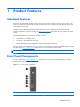
1 Product Features Standard Features Thank you for purchasing an HP thin client. We hope you have years of use from our thin clients. Our goal is to provide you with award-winning clients that are easy to deploy and manage with the power and reliability you expect. The next sections describe the features of the thin client. For a complete list of the hardware and software installed on a specific model, visit http://www.hp.com and search for your specific thin client model.
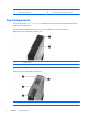
(2) Power button (5) Line-out (headphone) audio connector (3) Flash drive activity LED (6) Universal serial bus (USB) connectors (2) Top Components For more information, http://www.hp.com and search for your specific thin client model to find the model-specific QuickSpecs. The secure USB compartment allows you to use two USB devices in a secured location.
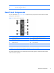
(2) Secure USB compartment ports (2) (3) USB cable management features Rear Panel Components For more information, http://www.hp.com and search for your specific thin client model to find the model-specific QuickSpecs.
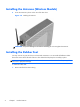
Installing the Antenna (Wireless Models) ▲ Screw the antenna in place on the rear of the thin client. Figure 1-5 Installing the antenna CAUTION: To prevent damage to the antenna mounting, do not overtighten the antenna. Installing the Rubber Feet You may want to use your thin client in a horizontal orientation. You can install self-adhesive rubber feet at the corners of the left side of the unit. The rubber feet help keep the unit safely in place.
2. Align the feet with their holes and press them in securely. Figure 1-6 Installing the rubber feet Installing the Stand If you want to use the thin client in a vertical orientation, you will need to install the stand for stability. To install the stand: 1. Turn unit upside down. 2. Position the stand with the wide part toward the front of the unit. Align the tabs on the stand with the slots on the bottom of the unit. 3.
Removing the Stand To remove the stand: 1. Turn unit upside down. 2. Press down on the tab (1), and then slide the stand toward the rear of the unit and pull it up to remove it from the unit (2). Figure 1-8 Removing the stand Using the Power Cord Retention Slot To prevent accidental disconnection, press a loop of the power cord into the power cord retention slot.
Using the Keyboard Figure 1-10 Keyboard features (1) Caps Lock key Activates/deactivates the Caps Lock feature. (2) Scroll Lock key Activates/deactivates the Scroll Lock feature. (3) Num Lock key Activates/deactivates the Num Lock feature. (4) Ctrl key Use in combination with another key; its function depends on the application software you are using. (5) Windows Logo Key12 Opens the Start menu in Microsoft® Windows®. Use in combination with other keys to perform other functions.
Windows Logo Key Use the Windows Logo Key in combination with other keys to perform certain functions available in Windows operating systems. Windows Logo Key + Tab Switch between open items. Windows Logo Key + e Open My Computer. Windows Logo Key + f Search for a file or folder. Windows Logo Key + Ctrl + f Search for computers. Windows Logo Key + m Minimize all windows. Windows Logo Key + Shift + m Undo minimize all. Windows Logo Key + Break Display the System Properties dialog box.
Serial Number Location Every thin client includes a unique serial number located as shown in the following illustration. Have this number available when contacting HP customer service for assistance.
2 Hardware Changes General Hardware Installation Sequence To ensure the proper installation thin client hardware components: 1. Back up any data, if necessary. 2. If the thin client is powered on: a. Turn off the computer properly through the operating system, then turn off any external devices. b. Disconnect the power cord from the power outlet and disconnect any external devices. c. Disconnect any external devices or cables, such as an antenna or cable lock.
9. Replace the secure USB compartment cover. See Removing and Replacing the Secure USB Compartment Cover on page 11. 10. Reconnect any external devices and power cords. 11. Turn on the monitor, the thin client, and any devices you want to test. 12. Load any necessary drivers. NOTE: You can download select hardware drivers from HP. Go to http://www.hp.com and search for your specific thin client model. 13. Reconfigure the thin client, if necessary.
2. Push the compartment cover about .6 cm (1/4 inch) toward the front of the unit (2) and lift it off the unit (3). Figure 2-1 Removing the secure USB compartment cover Replacing the Secure USB Compartment Cover To replace the secure compartment cover: 1. Place the cover on top of the unit so it is offset about 0.6 cm (1/4 inch) toward the front of the unit, allowing the tabs on the cover to align with the slots on the chassis (1). 2.
To remove the access panel: 1. Remove the secure compartment cover (1). For more information, see Removing the Secure USB Compartment Cover on page 11. 2. Remove the stand, if it is installed. See Removing the Stand on page 6 for more information. 3. Lay the unit flat on a stable surface with the right side up and the left side down. 4. Slide the access panel about 3 mm (1/8 inch) toward the top of the unit (2), and then lift the access panel up and off the unit (3).
Replacing the Metal Side Cover and Side Access Panel To replace the metal side cover: 1. Slip the front edge of the metal side cover under the lip on the chassis, lower the front edge, and then press the metal side cover down into place (1). 2. Insert and tighten the four screws (2). Figure 2-5 Replacing the metal side cover To replace the access panel: 14 1.
Installing Thin Client Options Various options can be installed on the thin client: ● Installing the USB Device on page 15 ● Removing and Replacing the Battery on page 16 ● Installing a Secondary Flash Memory Module on page 18 ● External Drives on page 19 Installing the USB Device Before beginning the replacement process, review General Hardware Installation Sequence on page 10 for procedures you should follow before and after installing or replacing hardware.
If you install a USB mouse and a USB keyboard in the secure USB compartment, route the cables around and through the clips, then out the secure cable routing slot, as shown in the following illustration. Figure 2-7 Using the secure cable routing slot Removing and Replacing the Battery Before beginning the replacement process, review General Hardware Installation Sequence on page 10 for procedures you should follow before and after installing or replacing hardware.
2. To release the battery from its holder, gently push the metal guard that extends above one edge of the battery very slightly toward the rear of the unit (1), then lift the battery out (2). NOTE: Be careful not to bend the metal guard. Figure 2-8 Removing and replacing the internal battery 3. To insert the new battery, align the replacement battery with the positive side toward the rear of the unit.
Installing a Secondary Flash Memory Module Before beginning the installation process, review General Hardware Installation Sequence on page 10 for procedures you should follow before and after installing or replacing hardware. WARNING! You must remove the right side panel to access the system board. Before removing the side access panel, ensure that the thin client is turned off and the power cord is disconnected from the electrical outlet.
External Drives Various external USB drives are available as options for these thin clients. For more information about these drives, visit http://www.hp.com and search for your specific thin client model, or refer to the instructions that accompany the option. For more information about available options, visit the HP Web sitehttp://www.hp.com and search for your specific thin client model.
A Specifications Table A-1 HP t510 Thin Client Dimensions Width 58.42 mm 2.30 in. Height (without stand) 209.55 mm 8.25 in Height (with stand) 219.70 mm 8.65 In Depth 215.90 mm 8.50 in. Approximate Weight 1.36 kg 3.00 lb 10° to 40° C 50° to 104° F -30° to 60° C -22° to 140° F Temperature Range (fanless design)* Operating** (max. rate of change is 10° C per hour or 18° F per hour) Nonoperating (max.
Table A-1 HP t510 Thin Client (continued) Rated Output Current (maximum) 3.42 A 3.
B Security Provisions Securing the Thin Client These thin clients are designed to accept a security cable lock. This cable lock prevents unauthorized removal of the thin client, as well as locking the secure compartment. To order this option, visit the HP Web site at http://www.hp.com and search for your specific thin client model. 1. Locate the cable lock slot on the back panel. 2. Insert the cable lock into the slot, and then use the key to lock it.
C Mounting the Thin Client HP Quick Release This thin client incorporates four mounting points on each side of the unit. These mounting points follow the VESA (Video Electronics Standards Association) standard, which provides industry-standard mounting interfaces for Flat Displays (FDs), such as flat panel monitors, flat displays, and flat TVs. The HP Quick Release connects to the VESA-standard mounting points, allowing you to mount the thin client in a variety of orientations.
To use the HP Quick Release: 1. Using four 15 mm screws included in the mounting device kit, attach one side of the HP Quick Release to the thin client as shown in the following illustration. Figure C-2 Connecting the HP Quick Release to the thin client 2. Using four screws included in the mounting device kit, attach the other side of the HP Quick Release to the device to which you will mount the thin client. Make sure the release lever points upward.
3. Slide the side of the mounting device attached to the thin client (1) over the other side of the mounting device (2) on the device on which you want to mount the thin client. An audible 'click' indicates a secure connection. Figure C-4 Connecting the thin client NOTE: When attached, the HP Quick Release automatically locks in position. You only need to slide the lever to one side to remove the thin client.
Figure C-6 Thin client mounted on back of monitor stand Figure C-7 Thin client mounted on wall Figure C-8 Thin client mounted under desk 26 Appendix C Mounting the Thin Client
Non-supported Mounting Option CAUTION: Mounting a thin client in an non-supported manner could result in failure of the HP Quick Release and damage to the thin client and/or other equipment. Do not mount the thin client on a flat panel monitor stand, between the panel and the stand.
D Thin Client Operation Routine Thin Client Care Use the following information to properly care for your thin client: 28 ● Never operate the thin client with the outside panel removed. ● Keep the thin client away from excessive moisture, direct sunlight, and extreme heat and cold. For information about the recommended temperature and humidity ranges for the thin client, see Specifications on page 20. ● Keep liquids away from the thin client and keyboard.
Supported Orientations HP supports the following orientations for the thin client. CAUTION: You must adhere to HP-supported orientations to ensure your thin clients function properly.
Non-supported Orientation HP does not support the following orientation for the thin client. CAUTION: Non-supported placement of thin clients could result in operation failure and/or damage to the devices. CAUTION: Thin clients require proper ventilation to maintain operating temperature. Do not block the vents. Do not put thin clients in drawers or other sealed enclosures. Do not place a monitor or other object on top of the thin client.
E Electrostatic Discharge A discharge of static electricity from a finger or other conductor may damage system boards or other static-sensitive devices. This type of damage may reduce the life expectancy of the device. Preventing Electrostatic Damage To prevent electrostatic damage, observe the following precautions: ● Avoid hand contact by transporting and storing products in static-safe containers. ● Keep electrostatic-sensitive parts in their containers until they arrive at static-free workstations.
F Shipping Information Shipping Preparation Follow these suggestions when preparing to ship the thin client: 1. Turn off the thin client and external devices. 2. Disconnect the power cord from the electrical outlet, then from the thin client. 3. Disconnect the system components and external devices from their power sources, then from the thin client. 4.
Index A access panel removing 12 replacing 14 altitude specifications 20 antenna installing 4 B battery, replacing front panel components 1 function keys 8 G grounding methods 31 16 C cable lock slot location 2 cable lock, installing 22 cable routing slot 3 cautions ambient temperature 11 antenna mounting 4 HP Quick Release 25 mounting thin client 27 static electricity 10 thin client orientation 29, 30 ventilation 30 components front panel 1 keyboard 7 mouse 8 rear panel 3 top 2 D dimensions 20 diskette
rear panel components 3 recycling 17 relative humidity specifications 20 removing battery 16 metal side cover 12 secure USB compartment cover 11 side access panel 12 stand 6 replacing battery 16 metal side cover 14 secure USB compartment cover 12 side access panel 14 retention slot, power cord 6 RJ-45 connector location 3 routine care 28 rubber feet, installing 4 S SATA flash memory module, installing 18 secure cable routing slot 3 secure USB compartment 22 location 1, 2 ports 2 removing cover 11 replacing