Hardware Reference Guide HP Compaq Pro 4300 All-in-One Business PC
© Copyright 2012 Hewlett-Packard Development Company, L.P. The information contained herein is subject to change without notice. Windows is either a trademark or registered trademark of Microsoft Corporation in the United States and/or other countries. Intel and Core are trademarks of Intel Corporation in the U.S. and other countries. Bluetooth is a trademark owned by its proprietor and used by Hewlett-Packard Company under license.
About This Book This guide provides basic information for upgrading this computer model. WARNING! Text set off in this manner indicates that failure to follow directions could result in bodily harm or loss of life. CAUTION: Text set off in this manner indicates that failure to follow directions could result in damage to equipment or loss of information. NOTE: Text set off in this manner provides important supplemental information.
iv About This Book
Table of contents 1 Product Features ............................................................................................................... 1 Overview ................................................................................................................................ 1 Front Components .................................................................................................................... 2 Side Components .....................................................................
vi
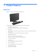
1 Product Features Overview Figure 1-1 HP Compaq Pro 4300 All-in-One Business PC The HP Compaq Pro 4300 All-in-One Business PC offers the following features: ● Integrated All-in-One form factor ● 20-inch diagonal widescreen 1600 x 900 WLED anti-glare display ● Adjustable tilt ● Removable panels on the back of the chassis allow users or technicians to easily and efficiently service the PC ● Optional integrated 1.
● Integrated Gigabit network connection (Realtek RTL81 11 F Gigabit Ethernet) ● Up to 16 GB of DDR3 SDRAM memory ● Optional wireless LAN (802.11 a/g/n, 802.
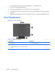
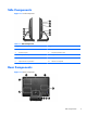
Side Components Figure 1-3 Side Components Table 1-2 Side Components Component Component 1 HP USB Media Card Reader 6 Optical disc drive activity LED 2 (2) USB 2.
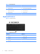
Table 1-3 Rear Components Component Component 1 Drive access panel 7 Security lock slot 2 Center access panel 8 Power connector with LED indicator 3 Memory access panel 9 RJ-45 Gigabit Ethernet port 4 Optical disc drive location 10 Stereo audio line out 5 Hard drive location 11 (4) USB 2.
Adjusting Tilt Tilt the computer forward up to -5 degrees or backward up to +25 degrees to set it to a comfortable eye level.
2 Hardware Repair and Upgrade Warnings and Cautions Before performing upgrades be sure to carefully read all of the applicable instructions, cautions, and warnings in this guide. WARNING! To reduce the risk of personal injury from electrical shock, hot surfaces, or fire: Disconnect the power cord from the wall outlet and allow the internal system components to cool before touching. Do not plug telecommunications or telephone connectors into the network interface controller (NIC) receptacles.
Additional Information For more information on removing and replacing hardware components, the Computer Setup utility, and troubleshooting, refer to the Maintenance and Service Guide (available in English only) for your computer model at http://www.hp.com. Connecting Power 1. Plug the power cord into the power connection on the rear of the computer (1). 2. Plug the three-pronged power plug into the power brick (2) and a power outlet (3). Figure 2-1 Connecting Power 3.
● Hard drive ● Optical disc drive Figure 2-2 Locating Internal Components Component Component 1 Optical disk drive 3 2 Hard drive Memory and battery compartment Removing and Installing Memory The computer comes with double data rate 3 synchronous dynamic random access memory (DDR3SDRAM) small outline dual inline memory modules (SODIMMs). The memory sockets on the system board can be populated with up to two industry-standard SODIMMs.
In addition, the computer supports: ● 512-Mbit, 1-Gbit, and 2-Gbit non-ECC memory technologies ● single-sided and double-sided SODIMMS ● SODIMMs constructed with x8 and x16 devices; SODIMMs constructed with x4 SDRAM are not supported NOTE: The system will not operate properly if you install unsupported SODIMMs. The system will automatically operate in single channel mode, dual channel mode, or flex mode, depending on how the SODIMMs are installed.
6. Remove the center access panel by pulling outward on the panel at the slot on the top edge of the panel. Figure 2-3 Removing the Center Access Panel 7. Open the latch securing the memory access panel.
8. To remove the memory access panel, press down on the tab on the inside edge of the panel (1) and slide the panel off the computer (2). Figure 2-5 Removing the Memory Access Panel 9. Pull upward on the raised tab on the memory cover and lift the cover off the computer.
10. To remove a memory module, press outward on the two latches on each side of the SODIMM (1), then pull the SODIMM out of the socket (2). Figure 2-7 Removing a Memory Module 11. To install a memory module, slide the SODIMM into the socket at approximately a 30° angle (1), then press the SODIMM down (2) so that the latches lock it in place (3). Figure 2-8 Installing a Memory Module NOTE: A memory module can be installed in only one way. Match the notch on the module with the tab on the memory socket.
12. Press the memory cover back in place. Insert the bottom edge of the memory cover into the sheet metal shielding first, then press the top edge of memory cover down. Ensure that all the tabs on the memory cover are pressed firmly against the sheet metal shielding. Figure 2-9 Replacing the Memory Cover 13.
15. To replace the center access panel, insert the bottom edge of the panel, then press down firmly on each side of the panel working from the bottom to the top so that the panel snaps securely in place. Figure 2-11 Replacing the Center Access Panel 16. Lock any security devices that were disengaged when the center access panel was removed. 17. Reconnect the power cord and external devices, then turn on the computer. The computer automatically recognizes the additional memory when you turn on the computer.
NOTE: The lifetime of the lithium battery can be extended by plugging the computer into a live AC wall socket. The lithium battery is only used when the computer is NOT connected to AC power. HP encourages customers to recycle used electronic hardware, HP original print cartridges, and rechargeable batteries. For more information about recycling programs, go to http://www.hp.com/ recycle. 1. Remove all removable media, such as compact discs or USB flash drives, from the computer. 2.
7. Open the latch securing the memory access panel. Figure 2-13 Opening the Memory Access Panel Latch 8. To remove the memory access panel, press down on the tab on the inside edge of the panel (1) and slide the panel off the computer (2).
9. Pull upward on the raised tab on the memory cover and lift the cover off the computer. Figure 2-15 Removing the Memory Cover 10. Depending on the type of battery holder on the system board, complete the following instructions to replace the battery. Type 1 a. Lift the battery out of its holder. Figure 2-16 Removing a Coin Cell Battery (Type 1) b. Slide the replacement battery into position, positive side up. The battery holder automatically secures the battery in the proper position. Type 2 a.
b. To insert the new battery, slide one edge of the replacement battery under the holder’s lip with the positive side up. Push the other edge down until the clamp snaps over the other edge of the battery (2). Figure 2-17 Removing and Replacing a Coin Cell Battery (Type 2) Type 3 a. Pull back on the clip (1) that is holding the battery in place, and remove the battery (2). b. Insert the new battery and position the clip back into place.
11. Press the memory cover back in place. Insert the bottom edge of the memory cover into the sheet metal shielding first, then press the top edge of memory cover down. Ensure that all the tabs on the memory cover are pressed firmly against the sheet metal shielding. Figure 2-19 Replacing the Memory Cover 12.
14. To replace the center access panel, insert the bottom edge of the panel, then press down firmly on each side of the panel working from the bottom to the top so that the panel snaps securely in place. Figure 2-21 Replacing the Center Access Panel 15. Lock any security devices that were disengaged when the center access panel was removed. 16. Reconnect the power cord and external devices, then turn on the computer. 17.
6. Remove the center access panel by pulling outward on the panel at the slot on the top edge of the panel. Figure 2-22 Removing the Center Access Panel 7. Open the latch securing the drive access panel.
8. To remove the drive access panel, push downward on the tab on the inside edge of the panel (1) and slide the panel off the computer (2). Figure 2-24 Removing the Drive Access Panel 9. Loosen the captive screw next to the front of the drive that secures the drive to the computer.
10. Grasp the handle on top of the hard drive cage (1) and slide the cage toward the outer edge of the computer, then lift the cage out of the computer (2). Figure 2-26 Removing the Hard Drive Cage 11. Remove the four mounting screws that secure the drive to the cage. Do not remove the blue rubber grommets behind each screw. They must stay attached to the cage when installing a new hard drive.
12. Slide the hard drive out of the cage. Figure 2-28 Removing the Hard Drive from the Cage 13. Slide the new hard drive into the cage, making sure that the connectors on the hard drive are at the opening of the cage. Figure 2-29 Sliding the Hard Drive into the Cage NOTE: If you choose to install an optional 2.5-inch solid state drive (SSD) or self-encrypting drive (SED), you must mount that drive in a drive adapter, and then install the assembly in the hard drive cage as you would a 3.5-inch hard drive.
14. Install the four mounting screws that secure the hard drive to the cage. Make sure that the blue rubber grommets remain attached to the cage behind each screw. Figure 2-30 Installing the Hard Drive Mounting Screws 15. Set the hard drive cage down into the bay so that the tabs on the bottom of the cage align with the slots on the chassis and slide the cage toward the center of the computer (1) so that the connector on the rear of the drive is securely seated.
16. Tighten the captive screw to secure the hard drive cage in place. Figure 2-32 Tightening the Hard Drive Security Screw 17. Place the drive access panel on the rear of the computer so that the edge of the panel is slightly hanging off the edge of the computer and slide the panel toward the center of the computer until it snaps in place. Figure 2-33 Replacing the Drive Access Panel 18. Rotate the drive panel latch up and close it to secure the drive access panel.
19. To replace the center access panel, insert the bottom edge of the panel, then press down firmly on each side of the panel working from the bottom to the top so that the panel snaps securely in place. Figure 2-34 Replacing the Center Access Panel 20. Lock any security devices that were disengaged when the center access panel was removed. 21. Reconnect the power cord and external devices, then turn on the computer.
6. Remove the center access panel by pulling outward on the panel at the slot on the top edge of the panel. Figure 2-35 Removing the Center Access Panel 7. Open the latch securing the drive access panel.
8. To remove the drive access panel, push downward on the tab on the inside edge of the panel (1) and slide the panel off the computer (2). Figure 2-37 Removing the Drive Access Panel 9. Remove the screw through the tab on the end of the drive that secures the drive to the computer.
10. Using your fingers, press the visible edge of the optical disc drive toward the side of the computer to push the drive partially out of the computer. Grasp the front end of the drive and pull the drive out of the computer. Figure 2-39 Removing the Optical Disc Drive 11. Align the new optical disc drive with the opening in the side of the computer. Push the drive in firmly until the edge is flush with the computer chassis. NOTE: The optical disc drive can be installed in only one way.
12. Replace the screw to secure the optical disc drive in place. Figure 2-41 Installing the Optical Disc Drive Security Screw 13. Place the drive access panel on the rear of the computer so that the edge of the panel is slightly hanging off the edge of the computer and slide the panel toward the center of the computer until it snaps in place. Figure 2-42 Replacing the Drive Access Panel 14. Rotate the drive panel latch up and close it to secure the drive access panel.
15. To replace the center access panel, insert the bottom edge of the panel, then press down firmly on each side of the panel working from the bottom to the top so that the panel snaps securely in place. Figure 2-43 Replacing the Center Access Panel 16. Lock any security devices that were disengaged when the center access panel was removed. 17. Reconnect the power cord and external devices, then turn on the computer.
A Electrostatic Discharge A discharge of static electricity from a finger or other conductor may damage system boards or other static-sensitive devices. This type of damage may reduce the life expectancy of the device. Preventing Electrostatic Damage To prevent electrostatic damage, observe the following precautions: ● Avoid hand contact by transporting and storing products in static-safe containers. ● Keep electrostatic-sensitive parts in their containers until they arrive at static-free workstations.
B Computer Operating Guidelines, Routine Care and Shipping Preparation Computer Operating Guidelines and Routine Care Follow these guidelines to properly set up and care for the computer: 34 ● Keep the computer away from excessive moisture, direct sunlight, and extremes of heat and cold. ● Operate the computer on a sturdy, level surface. Leave a 10.2-cm (4-inch) clearance on all vented sides of the computer to permit the required airflow.
Optical Disc Drive Precautions Be sure to observe the following guidelines while operating or cleaning the optical disc drive. ● Do not move the drive during operation. This may cause it to malfunction during reading. ● Avoid exposing the drive to sudden changes in temperature, as condensation may form inside the unit. If the temperature suddenly changes while the drive is on, wait at least one hour before you turn off the power. If you operate the unit immediately, it may malfunction while reading.
Index A additional information B battery replacement 7 14 M memory installing 8 removing 8 specifications 8 C components front 2 rear 3 side 3 components, internal 7 computer operating guidelines 34 O optical disc drive precautions 35 replacing 27 E electrostatic discharge, preventing damage 33 R rear components 3 removing battery 14 F features keyboard 4 overview 1 front components 2 S security lock location 32 shipping preparation 35 side components 3 specifications memory 8 G grounding methods