Hardware Reference Guide HP Compaq Elite 8300 Touch All-in-One Business PC HP Compaq Elite 8300 All-in-One Business PC HP Compaq Pro 6300 All-in-One Business PC
© Copyright 2012 Hewlett-Packard Development Company, L.P. The information contained herein is subject to change without notice. Windows is either a trademark or registered trademark of Microsoft Corporation in the United States and/or other countries. Intel and Core are trademarks of Intel Corporation in the U.S. and other countries. Bluetooth is a trademark owned by its proprietor and used by Hewlett-Packard Company under license.
About This Book This guide provides basic information for upgrading this computer model. WARNING! Text set off in this manner indicates that failure to follow directions could result in bodily harm or loss of life. CAUTION: Text set off in this manner indicates that failure to follow directions could result in damage to equipment or loss of information. NOTE: Text set off in this manner provides important supplemental information.
iv About This Book
Table of contents 1 Product Features ............................................................................................................... 1 Overview ................................................................................................................................ 1 Front Components .................................................................................................................... 3 Side Components .....................................................................
Appendix A Electrostatic Discharge .................................................................................... 48 Preventing Electrostatic Damage .............................................................................................. 48 Grounding Methods ............................................................................................................... 48 Appendix B Computer Operating Guidelines, Routine Care and Shipping Preparation ........
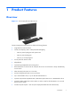
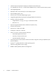
1 Product Features Overview Figure 1-1 HP Compaq All-in-One Business PC The HP Compaq All-in-One Business PC offers the following features: ● Integrated All-in-One form factor ● Full HD, LCD display (1920 x 1080) with LED backlighting ◦ 58.4-cm (23-inch) diagonal with optical touch ◦ 58.4-cm (23-inch) diagonal ◦ 54.6-cm (21.
2 ● Intel Q75 Express chipset (HP Compaq Pro 6300 All-in-One Business PC) ● Two SODIMM slots with up to 16 GB of DDR3 SDRAM memory and dual channel memory support ● Intel integrated graphics ● DisplayPort video out (with audio) for second display support ● Optional MXM graphics card ● DP audio, DP to VGA/DVI/HDMI dongle support ● Integrated Gigabit Ethernet (Intel 82579 LM Gigabit Network Connection) ● Wireless connectivity (optional): ◦ Integrated 802.
Front Components Figure 1-2 Front Components Table 1-1 Front Components Component Component 1 Webcam with privacy shutter (optional) 7 Mute speaker 2 Dual microphone array (optional) 8 Reduce volume 3 Webcam activity LED (with optional webcam) 9 Increase volume 4 16:9 widescreen LED-backlit LCD display 10 Mute microphone 5 Power LED 11 Decrease brightness 6 High-performance stereo speakers 12 Increase brightness Touch the icon area (7–12 above) to cause the icons to illuminate, th
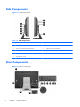
Side Components Figure 1-3 Side Components Table 1-2 Side Components Component Component 1 Hard disc drive activity LED 6 Tray-load optical disc drive 2 HP 6-in-1 media card reader (optional) 7 Optical disc drive eject button 3 (2) USB 3.
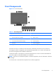
Table 1-3 Rear Components Component Component 1 Access panel 8 DisplayPort connector 2 Access panel latches 9 RJ-45 Gigabit Ethernet port 3 Security lock slot 10 Stereo audio line out 4 Power connector 11 Rear port cover 5 (2) PS/2 mouse and keyboard connectors 12 Serial port (optional) 6 (2) USB 2.0 ports 13 Access panel security screw 7 (2) USB 3.
Adjusting the Tilt/Swivel Base Tilt the computer forward up to -5 degrees or backward up to +30 degrees to set it to a comfortable eye level. Figure 1-6 Adjusting Tilt The tilt/swivel base has a swivel pad on the underside that allows you to swivel the computer up to 360 degrees left or right for the best viewing angle. Figure 1-7 Adjusting Swivel Height-adjustable/Recline Stand (Optional) An optional stand may be purchased to allow 6 ● height adjustment of 110 mm (4.
WARNING! If the height-adjustable/recline stand is installed, before laying the computer down for service, first grasp the sides of the display and raise the display to the highest position. Do not lay the computer down with the sliding stand in the low position. The stand may suddenly release, which could cause injury or damage to equipment.
2 Hardware Repair and Upgrade Warnings and Cautions Before performing upgrades be sure to carefully read all of the applicable instructions, cautions, and warnings in this guide. WARNING! To reduce the risk of personal injury from electrical shock, hot surfaces, or fire: Disconnect the power cord from the wall outlet and allow the internal system components to cool before touching. Do not plug telecommunications or telephone connectors into the network interface controller (NIC) receptacles.
Additional Information For more information on removing and replacing hardware components, the Computer Setup utility, and troubleshooting, refer to the Maintenance and Service Guide (available in English only) for your computer model at http://www.hp.com. Installing the Rear Port Cover 1. Ensure that all cables are connected. 2. Place the cover against the computer (1), lining up the cable lock slot in the cover about 12 mm (0.5 inch) below the cable lock slot in the computer.
2. Grasp the rear port cover, then pull it down and off the computer. Figure 2-2 Removing the Rear Port Cover Connecting Power 1. If the rear port cover is installed, remove the cover. 2. Route the power connector through the opening in the stand to take advantage of the cable management feature. 3. Plug the power cord into the power connection on the rear of the computer (1). 4. Plug the three-pronged power plug into a power outlet (2). Figure 2-3 Connecting Power 5.
6. Hold the cable management cover under the cables, align the cover hooks with the slots in the stand, then insert the cover and slide it down. Figure 2-4 Installing the Cable Management Cover 7. Replace the rear port cover. 8. Press the power button on the front of the computer to turn it on. Disconnecting Power 1. Remove all removable media, such as compact discs or USB flash drives, from the computer. 2.
Installing a Security Lock The optional security lock enables you to secure your computer from theft. A cable lock is a key lock device that has a wire cable attached. You attach one end of the cable to your desk (or other stationary object) and the other end of the cable to the cable lock slot on the computer. Secure the cable lock with the key. Figure 2-5 Installing a Cable Lock Installing an Access Panel Security Screw You may prevent access to internal components by securing the access panel.
Synchronizing the Optional Wireless Keyboard or Mouse The optional wireless keyboard and mouse are easy to set up. Just remove the battery tabs on both the keyboard and the mouse to activate the preinstalled batteries. Also, make sure the Power switch on the bottom of the mouse is in the On position (the keyboard does not have a Power switch). Then, turn on the computer and synchronize them as described below.
6. Press and release the Connect button on the bottom of the keyboard. The blue activity LED from the wireless receiver illuminates when the synchronization command has been received and turns off when synchronization is complete. Figure 2-8 Synchronizing the Wireless Keyboard and Mouse NOTE: If the procedure does not work, remove and then reinsert the wireless keyboard and mouse receiver from the back of the computer and then synchronize the keyboard and mouse again.
Figure 2-9 Removing Batteries from the Wireless Keyboard To remove batteries from the wireless mouse, remove the battery door on the underside of the mouse (1) and lift the batteries out of the battery compartment (2). Figure 2-10 Removing Batteries from the Wireless Mouse Attaching the Computer to a Mounting Fixture You can remove the computer from the stand and install it on a wall, monitor arm, or other mounting fixture.
HP Compaq Elite 8300 Touch All-in-One Business PC HP Compaq Pro 6300 All-in-One Business PC HP Compaq Elite 8300 All-in-One Business PC Computer Dimensions (without stand) Height 387.1 mm 15.2 in 367.4 mm 14.5 in Width 561.9 mm 22.1 in 521.9 mm 20.5 in Depth 65.0 mm 2.6 in 65.0 mm 2.6 in 6.63 kg 14.6 lb 7.88 kg 17.4 lb 100 mm x 100 mm 3.94 in x 3.94 in Computer Weight (without stand) Minimum Configuration 7.65 kg (8300 Touch) 16.9 lb (8300 Touch) 6.60 kg (8300) 14.
6. Push the release button (1) on the bottom of the stand and pull the back of the stand off (2). Figure 2-11 Removing the back of the Stand 7. Push the base of the stand down (1), and loosen the captive screws securing the stand to the unit (2).
8. Lift the stand up and off the computer to expose the VESA mounting holes. Figure 2-13 Removing the Stand The computer is now ready to be attached to a VESA-compliant mounting fixture. Figure 2-14 VESA Mounting Holes Connecting a Second Display The DisplayPort connector on the rear of the computer allows you to connect a second display to the computer. If you are adding a second display that has a DisplayPort connector, then no DisplayPort video adapter is required.
To connect a second display: 1. Turn off power to the computer and the second display that you are connecting to the computer. 2. Remove the rear port cover on the computer. 3. If your second display has a DisplayPort connector, connect a DisplayPort cable directly between the DisplayPort connector on the rear of the computer and the DisplayPort connector on the second display.
4. If your second display does not have a DisplayPort connector, connect a DisplayPort video adapter to the DisplayPort connector of the computer. Then connect a cable (VGA, DVI. or HDMI, depending on your application) between the adapter and a second display. NOTE: When a display port adaptor is used, the rear port cover cannot be installed unless a display port extender cable is used in conjunction with the adaptor. Figure 2-17 Connecting a Second Display Using a DisplayPort Adapter 5.
● Hard disc drive, solid state drive, or self-encrypting drive ● Optical disc drive Figure 2-18 Locating Internal Components Component Component 1 Optical disc drive 4 Memory 2 Hard disc drive 5 mSATA connector 3 Battery Removing and Installing Memory The computer comes with double data rate 3 synchronous dynamic random access memory (DDR3SDRAM) small outline dual inline memory modules (SODIMMs).
The DDR3-SDRAM SODIMMs must also: ● support CAS latency 11 DDR3 1600 MHz (11-11-11 timing) ● contain the mandatory Joint Electronic Device Engineering Council (JEDEC) specification In addition, the computer supports: ● 1-Gbit, 2-Gbit, and 4-Gbit non-ECC memory technologies ● single-sided and double-sided SODIMMS ● SODIMMs constructed with x8 and x16 SDRAMs; SODIMMs constructed with x4 SDRAMs are not supported NOTE: The system will not operate properly if you install unsupported SODIMM memory.
Populating SODIMM Sockets The system will automatically operate in single channel mode, dual channel mode, or flex mode, depending on how the SODIMMs are installed. Refer to the following table to identify the SODIMM channel locations. Table 2-1 Identifying SODIMM Locations Location System Board Label Channel Lower Socket SODIMM1 Channel A Upper Socket SODIMM3 Channel B ● The system will operate in single channel mode if the SODIMM sockets are populated in one channel only.
6. Slide the access panel latches toward the edges of the unit, then slide the access panel toward the top of the computer until it slides off the unit. Figure 2-19 Removing the Access Panel 7. To remove a memory module, press outward on the two latches on each side of the SODIMM (1), then pull the SODIMM out of the socket (2).
8. To install a memory module, slide the SODIMM into the socket at approximately a 30° angle (1), then press the SODIMM down (2) so that the latches lock it in place. Figure 2-21 Installing a Memory Module NOTE: A memory module can be installed in only one way. Match the notch on the module with the tab on the memory socket. 9. To replace the access panel, set the panel on the back of the computer, slightly above the stand, and slide it down into place. Figure 2-22 Replacing the Access Panel 10.
equivalent to the battery originally installed in the computer. The computer comes with a 3-volt lithium coin cell battery. WARNING! The computer contains an internal lithium manganese dioxide battery. There is a risk of fire and burns if the battery is not handled properly. To reduce the risk of personal injury: Do not attempt to recharge the battery. Do not expose to temperatures higher than 60 °C (140 ºF). Do not disassemble, crush, puncture, short external contacts, or dispose of in fire or water.
6. Slide the access panel latches toward the edges of the chassis, then slide the access panel toward the top of the computer until it slides off the chassis. Figure 2-23 Removing the Access Panel The battery can now be seen on the lower right side of the fan. Figure 2-24 Locating the Battery 7. To release the battery from its holder, squeeze the metal clamp that extends above one edge of the battery. When the battery pops up, lift it out (1).
8. To insert the new battery, slide one edge of the replacement battery under the holder’s lip with the positive side up. Push the other edge down until the clamp snaps over the other edge of the battery (2). Figure 2-25 Removing and Replacing a Coin Cell Battery (Type 2) 9. To replace the access panel, set the panel on the back of the computer, slightly above the stand, and slide it down into place. Figure 2-26 Replacing the Access Panel 10. Reconnect the power cord and external devices. 11.
Replacing Drives Replacing the Hard Disc Drive with a 3.5-inch Hard Disc Drive or a Single 2.5-inch Drive The hard disc drive is located behind the access panel on the left side of the computer (when viewed from behind). The drive is housed in a removable cage. If you choose to install an optional 2.5-inch solid state drive (SSD) or self-encrypting drive (SED), you will need a drive adapter. The drive adapter may be part of the drive kit, or you may need to purchase it separately.
7. Pull the latch next to the lower side of the hard disc drive cage away from the cage to release it, then slide the cage toward the edge of the chassis and lift it out. Figure 2-28 Removing the Hard Disc Drive Cage 8. Lift the latch on one side of the hard disc drive cage and pull the hard disc drive out of the cage.
9. Remove the four mounting screws from the hard disc drive. Be sure to keep the blue rubber grommets with each screw. Figure 2-30 Removing the Mounting Screws 10. Screw the four mounting screws into the new hard disc drive. Be sure to keep the blue rubber grommets behind each screw. Figure 2-31 Inserting the Mounting Screws NOTE: If you choose to install an optional 2.5-inch solid state drive (SSD) or self-encrypting drive (SED), you must 1. mount the drive in a drive adapter 2.
11. Slide the new hard disc drive, or drive adapter holding an optional 2.5-inch drive, into the cage until it snaps in place. Be sure that the connector on the hard disc drive is at the opening of the cage. Figure 2-32 Inserting the Hard Disc Drive into the Cage 12. With the hard disc drive connector facing toward the center of the chassis, place the hard disc drive cage into the chassis and slide it toward the center until it snaps into place.
13. To replace the access panel, set the panel on the back of the computer, slightly above the stand, and slide it down into place. Figure 2-34 Replacing the Access Panel 14. Reconnect the power cord and external devices. 15. Lock any security devices that were disengaged when the access panel was removed. 16. Turn on the computer. Replacing the Hard Disc Drive with Two 2.5-inch Drives The hard disc drive is located behind the access panel on the left side of the computer (when viewed from behind).
6. Slide the access panel latches toward the edges of the chassis, then slide the access panel toward the top of the computer until it slides off the chassis. Figure 2-35 Removing the Access Panel 7. Push the release button (1) on the bottom of the stand and pull the back of the stand off (2).
8. Push the base of the stand down (1), and loosen the captive screws securing the stand to the chassis (2). Figure 2-37 Releasing the Stand 9. Lift the stand up and off the computer.
10. Remove the screw (1) in the middle of the lower panel, and detach the lower panel from the chassis (2). Figure 2-39 Removing the Lower Panel 11. Remove the screws securing the metal plate to the chassis.
12. Slide the metal plate left (1), then lift it off the chassis (2). Figure 2-40 Removing the Metal Plate 13. Pull the latch next to the lower side of the hard disc drive cage away from the cage to release it, then slide the cage toward the edge of the chassis and lift it out.
14. Lift the latch on one side of the hard disc drive cage and pull the hard disc drive out of the cage. Figure 2-42 Removing the Hard Disc Drive from the Cage 15. Remove the four mounting screws from the hard disc drive. Be sure to keep the blue rubber grommets with each screw. Figure 2-43 Removing the Mounting Screws 16. Mount the 2.5-inch drives in a drive adapter.
17. Screw the four mounting screws into the drive adapter holding the two 2.5-inch drives. Be sure to keep the blue rubber grommets behind each screw. Figure 2-44 Inserting the Mounting Screws 18. Slide the drive adapter into the cage until it snaps in place. Be sure that the connectors on the hard disc drives are at the opening of the cage.
19. With the hard disc drive connectors facing toward the center of the chassis, place the hard disc drive cage into the chassis and slide it toward the center until it snaps into place. Figure 2-46 Installing the Hard Disc Drive Cage 20. Connect the SATA cable to the blue SATA 1 connector and to the power connector next to the SATA 1 connector on the system board.
21. Be sure that excess cable length is out of the way and that cables are laying flat across the power supply. Connect the cable to the top drive. Figure 2-48 Connecting the Top 2.5-inch Drive 22. Keeping the cables flat, match up the four holes in the plate with the four posts and set the metal plate on the chassis. Slide the plate firmly to the right to secure the plate.
23. Secure the metal plate to the chassis with the screws previously removed. 24. Slide the lower panel up onto the chassis (1), engaging the hooks on the lower edge. Be sure that the VESA mounting posts protrude through the corner holes of the center square and that the center hole is lined up with the screw hole. Figure 2-50 Replacing the Lower Panel 25. Secure the lower panel to the chassis with the screw (2).
26. Engage the hooks in the top of the stand in the two large holes in the top of the lower panel, and lower the stand onto the computer. Figure 2-51 Replacing the Stand 27. Tighten the captive screws to secure the stand to the chassis. 28. Align the top of the back of the stand with the stand, and press it into place, working along the sides until it is in place.
29. To replace the access panel, set the panel on the back of the computer, slightly above the stand, and slide it down into place. Figure 2-53 Replacing the Access Panel 30. Reconnect the power cord and external devices. 31. Lock any security devices that were disengaged when the access panel was removed. 32. Turn on the computer. Replacing the Optical Disc Drive The optical disc drive is located above the hard disc drive on the left side of the computer (when viewed from behind). 1.
6. Slide the access panel latches toward the edges of the chassis, then slide the access panel toward the top of the computer until it slides off the chassis. Figure 2-54 Removing the Access Panel 7. Lift the tab at the back of the optical disc drive enclosure to release the drive.
8. Remove the two screws securing the optical disc drive bracket to the drive. Figure 2-56 Removing the Optical Disc Drive Bracket 9. Secure the optical disc drive bracket to the new drive with the two screws.
10. Align the new optical disc drive with the opening in the side of the computer. Push the drive in firmly until it snaps into place. NOTE: The optical disc drive can be installed in only one way. Figure 2-58 Installing the Optical Disc Drive 11. To replace the access panel, set the panel on the back of the computer, slightly above the stand, and slide it down into place. Figure 2-59 Replacing the Access Panel 12. Reconnect the power cord and external devices. 13.
A Electrostatic Discharge A discharge of static electricity from a finger or other conductor may damage system boards or other static-sensitive devices. This type of damage may reduce the life expectancy of the device. Preventing Electrostatic Damage To prevent electrostatic damage, observe the following precautions: ● Avoid hand contact by transporting and storing products in static-safe containers. ● Keep electrostatic-sensitive parts in their containers until they arrive at static-free workstations.
B Computer Operating Guidelines, Routine Care and Shipping Preparation Computer Operating Guidelines and Routine Care Follow these guidelines to properly set up and care for the computer: ● Keep the computer away from excessive moisture, direct sunlight, and extremes of heat and cold. ● Operate the computer on a sturdy, level surface. Leave a 10.2-cm (4-inch) clearance on all vented sides of the computer to permit the required airflow.
Optical Disc Drive Precautions Be sure to observe the following guidelines while operating or cleaning the optical disc drive. ● Do not move the drive during operation. This may cause it to malfunction during reading. ● Avoid exposing the drive to sudden changes in temperature, as condensation may form inside the unit. If the temperature suddenly changes while the drive is on, wait at least one hour before you turn off the power. If you operate the unit immediately, it may malfunction while reading.
Index A additional information B battery replacement 9 25 C components front 3 internal 20 rear 4 side 4 computer operating guidelines 49 D DisplayPort video adapter, connecting 18 E electrostatic discharge, preventing damage 48 F features keyboard 5 overview 1 front components 3 G grounding methods 48 H hard disc drive, replacing 29 height adjustment 6 I installation guidelines 8 installing 2.5-inch drive, single 29 2.5-inch drives, two 33 3.