Hardware Reference Guide HP t505 Flexible Thin Client
© Copyright 2013 Hewlett-Packard Development Company, L.P. The information contained herein is subject to change without notice. Microsoft and Windows are trademarks of Microsoft Corporation in the U.S. and other countries. The only warranties for HP products and services are set forth in the express warranty statements accompanying such products and services. Nothing herein should be construed as constituting an additional warranty.
About This Book WARNING! Text set off in this manner indicates that failure to follow directions could result in bodily harm or loss of life. CAUTION: Text set off in this manner indicates that failure to follow directions could result in damage to equipment or loss of information. NOTE: Text set off in this manner provides important supplemental information. If you have comments, feedback, or questions about this guide, please e-mail us at thinclientdocs@hp.com.
iv About This Book
Table of contents 1 Product Features ............................................................................................................... 1 Standard Features .................................................................................................................... 1 Front Panel Components ........................................................................................................... 2 Rear Panel Components .....................................................................
Supported Placement .............................................................................................................. 32 Non-supported Placement ....................................................................................................... 34 Appendix E Electrostatic Discharge ..................................................................................... 35 Preventing Electrostatic Damage ...........................................................................................
1 Product Features Standard Features Thank you for purchasing an HP thin client. We hope you have years of use from our thin clients. Our goal is to provide you with award-winning clients that are easy to deploy and manage with the power and reliability you expect. The next sections describe the features of the thin client. For a complete list of the hardware and software installed on a specific model, visit http://www.hp.com and search for your specific thin client model.
Front Panel Components For more information, go to http://www.hp.com and search for your specific thin client model to find the model-specific QuickSpecs.
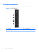
Rear Panel Components For more information, go to http://www.hp.com and search for your specific thin client model to find the model-specific QuickSpecs. Figure 1-2 Rear panel components (1) Ethernet RJ-45 connector (5) Cable lock slot (2) Serial connectors (4) (6) Power connector (3) Parallel connector (7) VGA connector (4) PS/2 connectors (2) (8) Universal serial bus (USB) connectors (2) Installing the Rubber Feet You may want to use your thin client in a horizontal orientation.
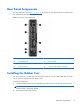
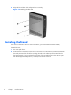
3. Align the feet with their holes and press them in securely. Figure 1-3 Installing the rubber feet Installing the Stand If you wish to use the thin client in a vertical orientation, you should install the stand for stability. To install the stand: 4 1. Turn unit upside down. 2. Locate the slots on the bottom of the unit into which the tabs on the stand fit. Position the stand with the wide part toward the front of the unit.
3. Insert the tabs into the slots and slide the stand forward until it locks into place. Figure 1-4 Installing the stand Removing the Stand To remove the stand: 1. Turn unit upside down. 2. Press the tab (1), then slide the stand toward the rear of the thin client and lift it off the unit (2).
Using the Keyboard Figure 1-6 Keyboard features (1) Caps Lock key Activates/deactivates the Caps Lock feature. (2) Scroll Lock key Activates/deactivates the Scroll Lock feature. (3) Num Lock key Activates/deactivates the Num Lock feature. (4) Ctrl key Use in combination with another key; its function depends on the application software you are using. (5) Microsoft® Windows® Logo Key1,2 Opens the Start menu in Windows. Use in combination with other keys to perform other functions.
Windows Logo Key Use the Windows Logo Key in combination with other keys to perform certain functions available in Windows operating systems. Windows Logo Key + Tab Switch between open items. Windows Logo Key + e Open My Computer. Windows Logo Key + f Search for a file or folder. Windows Logo Key + Ctrl + f Search for computers. Windows Logo Key + m Minimize all windows. Windows Logo Key + Shift + m Undo minimize all. Windows Logo Key + Break Display the System Properties dialog box.
Serial Number Location Every thin client includes a unique serial number located as shown in the following illustration. Have this number available when contacting HP customer service for assistance.
2 Hardware Changes General Hardware Installation Sequence To ensure the proper installation thin client hardware components: 1. Back up any data, if necessary. 2. If the thin client is powered on: a. Turn off the computer properly through the operating system, then turn off any external devices. b. Disconnect the power cord from the power outlet and disconnect any external devices. c. Disconnect any external devices or cables, such as a cable lock.
Removing and Replacing the Side Access Panel Removing the Side Access Panel WARNING! Before removing the side access panel, ensure that the thin client is turned off and the power cord is disconnected from the electrical outlet. To remove the access panel: 1. Lay the unit flat on a stable surface with the right side up and the left side down. 2. Remove the two screws that secure the access panel to the chassis (1). 3. Slide the access panel about 8.
Replacing the Side Access Panel To replace the access panel: 1. Align the tabs on the access panel with the slots in the both sides of the chassis and place the access panel on the side of the unit, offset about 8.3 mm (1/3 inch) toward the top of the unit (1). 2. Slide the panel toward the front of the unit until the panel is flush with the bottom panel of the chassis (2). 3. Insert and fasten the two screws to secure the side access panel to the chassis.
Installing Thin Client Options Various options can be installed on the thin client: ● Removing and Replacing the Battery on page 12 ● External Drives on page 13 Removing and Replacing the Battery Before beginning the replacement process, review General Hardware Installation Sequence on page 9 for procedures you should follow before and after installing or replacing hardware.
The Taiwan EPA requires dry battery manufacturing or importing firms, in accordance with Article 15 or the Waste Disposal Act, to indicate the recovery marks on the batteries used in sales, giveaways, or promotions. Contact a qualified Taiwanese recycler for proper battery disposal. External Drives Various external USB drives are available as options for these thin clients. For more information about these drives, visit http://www.hp.
Figure 2-4 Serial Port Jumper Locations on the System Board Item Jumper 1 COM3 SP33 2 COM3 SP31 3 COM4 SP43 4 COM4 SP41 5 COM2 SP28 6 COM2 SP23 7 COM2 SP21 8 COM2 SP22 9 COM2 SP24 10 COM2 SP29 11 COM4 SP42 12 COM4 SP44 13 COM3 SP32 14 COM3 SP34 Before beginning the configuration process, review General Hardware Installation Sequence on page 9 for procedures you should follow before and after installing or replacing hardware.
To configure the serial ports: 1. Locate the serial port and jumper. 2. Place jumpers on the appropriate pins. (See Table 2-3 Configuring Serial Port Power on page 16 to determine the appropriate pins.) CAUTION: An unsupported configuration can cause severe equipment damage. Carefully verify COM Port Jumper locations and supported configurations before you configure a serial port.
CAUTION: To prevent severe equipment damage, carefully verify the location of the COM Port Jumper before you configure it. See Figure 2-4 Serial Port Jumper Locations on the System Board on page 14 for locations. NOTE: The jumpers in the following table are in the same orientation illustrated in Figure 2-4 Serial Port Jumper Locations on the System Board on page 14.
Table 2-3 Configuring Serial Port Power (continued) Configuring Powered Serial Ports 17
Table 2-3 Configuring Serial Port Power (continued) 18 Chapter 2 Hardware Changes
Table 2-3 Configuring Serial Port Power (continued) Configuring Powered Serial Ports 19
Table 2-3 Configuring Serial Port Power (continued) 20 Chapter 2 Hardware Changes
Table 2-3 Configuring Serial Port Power (continued) Configuring Powered Serial Ports 21
A Specifications Table A-1 HP t505 Flexible Thin Client Dimensions Width 50.00 mm 1.97 in. Height (without stand) 220.00 mm 8.66 in Height (with stand) 228.50 mm 9.00 in Depth 194.00 mm 7.74 in. Approximate Weight (without adapter) 1.483 kg 3.27 lb Adapter 0.336 kg 0.74 lb 10° to 35° C 50° to 95° F -30° to 60° C -22° to 140° F Temperature Range (fanless design)* Operating** (max. rate of change is 10° C per hour or 18° F per hour) Nonoperating (max.
Table A-1 HP t505 Flexible Thin Client (continued) Rated Output Current (maximum) 3.42 A 3.
B Security Provisions Securing the Thin Client These thin clients are designed to accept a security cable lock. This cable lock prevents unauthorized removal of the thin client. To order this option, visit the HP website at http://www.hp.com and search for your specific thin client model. 1. Locate the cable lock slot on the back panel. 2. Insert the cable lock into the slot, and then use the key to lock it.
C Mounting the Thin Client HP Quick Release This thin client incorporates four mounting points on each side of the unit. These mounting points follow the VESA (Video Electronics Standards Association) standard, which provides industry-standard mounting interfaces for Flat Displays (FDs), such as flat panel monitors, flat displays, and flat TVs. The HP Quick Release connects to the VESA-standard mounting points, allowing you to mount the thin client in a variety of orientations.
To use the HP Quick Release: 1. Using four 10 mm screws included in the mounting device kit, attach one side of the HP Quick Release to the thin client as shown in the following illustration. Figure C-2 Connecting the HP Quick Release to the thin client 2. Using four screws included in the mounting device kit, attach the other side of the HP Quick Release to the device to which you will mount the thin client. Make sure the release lever points upward.
3. Slide the side of the mounting device attached to the thin client (1) over the other side of the mounting device (2) on the device on which you want to mount the thin client. An audible 'click' indicates a secure connection. Figure C-4 Connecting the thin client NOTE: When attached, the HP Quick Release automatically locks in position. You only need to slide the lever to one side to remove the thin client.
Figure C-6 Thin client mounted on back of monitor stand Figure C-7 Thin client mounted on wall 28 Appendix C Mounting the Thin Client
Figure C-8 Thin client mounted under desk HP Quick Release 29
Non-supported Mounting Option CAUTION: Mounting a thin client in an non-supported manner could result in failure of the HP Quick Release and damage to the thin client and/or other equipment. Do not mount the thin client on a flat panel monitor stand, between the panel and the stand.
D Thin Client Operation Routine Thin Client Care Use the following information to properly care for your thin client: ● Never operate the thin client with the outside panel removed. ● Keep the thin client away from excessive moisture, direct sunlight, and extreme heat and cold. For information about the recommended temperature and humidity ranges for the thin client, see Specifications on page 22. ● Keep liquids away from the thin client and keyboard.
Supported Placement HP supports placement of the thin client as follows: CAUTION: You must adhere to HP-supported placement to ensure your thin clients function properly.
Figure D-3 Under monitor stand with at least one inch clearance Supported Placement 33
Non-supported Placement HP does not support placement of the thin client as follows. CAUTION: Non-supported placement of thin clients could result in operation failure and/or damage to the devices. CAUTION: Thin clients require proper ventilation to maintain operating temperature. Do not block the vents. Do not put thin clients in drawers or other sealed enclosures. Do not place a monitor or other object on top of the thin client. Thin clients require proper ventilation to maintain operating temperatures.
E Electrostatic Discharge A discharge of static electricity from a finger or other conductor may damage system boards or other static-sensitive devices. This type of damage may reduce the life expectancy of the device. Preventing Electrostatic Damage To prevent electrostatic damage, observe the following precautions: ● Avoid hand contact by transporting and storing products in static-safe containers. ● Keep electrostatic-sensitive parts in their containers until they arrive at static-free workstations.
F Shipping Information Shipping Preparation Follow these suggestions when preparing to ship the thin client: 1. Turn off the thin client and external devices. 2. Disconnect the power cord from the electrical outlet, then from the thin client. 3. Disconnect the system components and external devices from their power sources, then from the thin client. 4.
Index A access panel removing 10 replacing 11 altitude specifications 22 B battery, replacing hardware drivers 9 hardware specifications 22 hardware, upgrades 9 headphone connector location horizontal orientation 3 horizontal placement 32 HP Quick Release 25 humidity specifications 22 12 C cable lock, installing 24 cable routing slot 3 cautions HP Quick Release 27 mounting thin client 30 static electricity 9 thin client orientation 34 thin client placement 32 ventilation 34 components front panel 2 keybo
S secure cable routing slot 3 security 24 serial connector location 3 serial connectors 13 serial number location 8 service repair 36 shipping preparation 36 shutting down 9 side access panel replacing 11 specifications altitude 22 dimensions 22 hardware 22 humidity 22 power output 22 power supply 22 rated output current 23 relative humidity 22 temperature 22 thin client 22 weight 22 stand installing 4 removing 5 supported mounting options 27 supported placement 32 horizontal 32 under monitor stand 32 verti