Hardware Reference Guide HP t610 Series Flexible Thin Clients
© Copyright 2012 Hewlett-Packard Development Company, L.P. The information contained herein is subject to change without notice. Microsoft and Windows are trademarks of Microsoft Corporation in the U.S. and other countries. The only warranties for HP products and services are set forth in the express warranty statements accompanying such products and services. Nothing herein should be construed as constituting an additional warranty.
About This Book WARNING! Text set off in this manner indicates that failure to follow directions could result in bodily harm or loss of life. CAUTION: Text set off in this manner indicates that failure to follow directions could result in damage to equipment or loss of information. NOTE: Text set off in this manner provides important supplemental information.
iv About This Book
Table of contents 1 Product features ............................................................................................................... 1 Standard features ..................................................................................................................... 1 Front panel components ............................................................................................................ 1 Rear panel components ...................................................................
Appendix C Mounting the thin client .................................................................................. 30 HP Quick Release .................................................................................................................. 30 Supported mounting options .................................................................................................... 32 Appendix D Thin client operation .......................................................................................
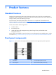
1 Product features Standard features Thank you for purchasing an HP thin client. We hope you have years of use from our HP t610 Series Flexible Thin Clients. Our goal is to provide you with award-winning clients that are easy to deploy and manage with the power and reliability you expect. The next sections describe the features of the thin clients. For a complete list of the hardware and software installed on a specific model, visit http://h10010.www1.hp.
(3) Line-in (microphone) connector For more information, refer to the model-specific QuickSpecs at http://h18004.www1.hp.com/products/quickspecs/ QuickSpecs_Archives/QuickSpecs_Archives.html.
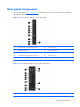
Rear panel components For more information, http://www.hp.com and search for your specific thin client model to find the model-specific QuickSpecs. Figure 1-2 HP t610 Thin Client rear panel components (1) DVI-I connector for DVI-D and VGA output (6) Serial connector (2) DisplayPort connector (7) PS/2 connectors (2) (3) Ethernet RJ-45 connector (8) Power cord retention slot (4) Universal serial bus (USB) connectors (2) 2.0 (9) Cable lock slot (5) Universal serial bus (USB) connectors (2) 3.
(2) DisplayPort connector (8) Power cord retention slot (3) Ethernet RJ-45 connector (9) Cable lock slot (4) Universal serial bus (USB) connectors (2) 2.0 (10) Parallel connector (5) Universal serial bus (USB) connectors (2) 3.
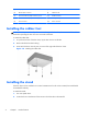
3. Insert the tabs into the slots, and then slide the stand about 1.26 cm (1/2 inch) toward the front of the unit until it locks into place. Figure 1-5 Installing the stand Removing the stand To remove the stand: 1. Turn unit upside down. 2. Press the tab (1), and then slide the stand about 1.26 cm (1/2 inch) toward the back of the unit and lift the stand off the unit (2).
Using the power cord retention slot To prevent accidental disconnection, press a loop of the power cord into the power cord retention slot. Figure 1-7 Power cord retention slot (HP t610 PLUS Thin Client pictured in horizontal orientation) Using the keyboard Figure 1-8 Keyboard features 6 (1) Caps Lock key Activates/deactivates the Caps Lock feature. (2) Scroll Lock key Activates/deactivates the Scroll Lock feature. (3) Num Lock key Activates/deactivates the Num Lock feature.
(6) Alt key Use in combination with another key; its function depends on the application software you are using. (7) Application key1 Similar to the right mouse button, opens pop-up menus in a Microsoft Office application. May perform other functions in other software applications. (8) Editing keys Includes the following: Insert, Home, Page Up, Delete, End, and Page Down. Hold Ctrl and Alt while pressing Delete to restart the thin client. 1 Available in select geographic regions.
Windows logo key Use the Windows Logo Key in combination with other keys to perform certain functions available in Windows operating systems. Windows Logo Key + Tab Switch between open items. Windows Logo Key + e Open My Computer. Windows Logo Key + f Search for a file or folder. Windows Logo Key + Ctrl + f Search for computers. Windows Logo Key + m Minimize all windows. Windows Logo Key + Shift + m Undo minimize all. Windows Logo Key + Break Display the System Properties dialog box.
Serial number location Every thin client includes a unique serial number located as shown in the following illustration. Have this number available when contacting HP customer service for assistance.
2 Hardware changes General hardware installation sequence To ensure the proper installation thin client hardware components: 1. Back up any data, if necessary. 2. If the thin client is powered on: a. Turn the unit and any other attached devices off. b. Disconnect the power cord from the wall outlet. c. Disconnect any external devices or cables, such as a cable lock.
8. Install the stand, if you will be using the thin client unmounted in a vertical orientation. See Installing the stand on page 4 for more information. 9. Reconnect any external devices and power cords. 10. Turn on the monitor, the thin client, and any devices you want to test. 11. Load any necessary drivers. NOTE: You can download select hardware drivers from HP at http://www.hp.com/country/us/ eng/support.html. 12. Reconfigure the thin client, if necessary.
4. ◦ Install or remove an internal hard drive ◦ Install or remove a PCI Express card Slide the access panel about 6.35 mm (1/4 inch) toward the bottom of the unit, and then lift the access panel up and off the chassis. Figure 2-2 Removing the side access panel Removing the left metal side cover NOTE: Do not remove the metal side cover to install a SODIMM. The SODIMM compartment is in the right side of the chassis.
Replacing the left metal side cover 1. Place the metal side cover on the chassis, rear edge first, making sure to insert the two tabs of the rear edge into the notches in the chassis (1). 2. Align the tabs on both sides of the cover and press the front edge down firmly until the latch closes. Figure 2-4 Replacing the metal side cover Replacing the side access panel To replace the access panel: 1. Place the access panel on the side of the unit, offset about 6.
3. Turn the chassis upside down. Align the hooks on the underside of the bottom cover with the slots in the chassis and press the cover down and then forward until it locks in place. Figure 2-6 Replacing the bottom cover 4. Replace the stand, if the thin client is to be used in the tower orientation.
2. To remove the battery, pull the metal clamp extending above the battery aside and lift the battery out (1). Figure 2-7 Removing and replacing the internal battery 3. To insert the replacement battery, position it with the positive side facing the chassis wall. Slide the battery down into the slot until the clamp snaps over the edge of the battery (2). HP encourages customers to recycle used electronic hardware, HP original print cartridges, and rechargeable batteries.
Installing a SODIMM The computer comes with double data rate 3 synchronous dynamic random access memory (DDR3SDRAM) small outline dual inline memory modules (SODIMMs). The memory sockets on the system board can be populated with up to two industry-standard SODIMMs. These memory sockets are populated with at least one preinstalled SODIMM. To achieve the maximum memory support, you can populate the system board with up to 4 GB of memory.
NOTE: Populate the SODIMM sockets in the following order: SODIMM1, then SODIMM2. 1. Slide the serial number tab out of the way. NOTE: Be sure not to lose this tab. 2. Pull the front of the access plate up, and lift it off the thin client. Figure 2-8 Removing the SODIMM access plate 3. Align the notched edge of the SODIMM with the tab in the socket. CAUTION: To prevent damage to the SODIMM, hold it by the edges only. Do not touch the components on the SODIMM, and do not bend the SODIMM. 4.
5. Press the SODIMM down into the compartment (2). 6. If you are installing the SODIMM in the HP t610 Thin Client, place a thermal pad on the SODIMM. CAUTION: The thermal pad is required to help cool the SODIMM in the HP t610 Thin Client. (The HP t610 PLUS Thin Client does not require a thermal pad.) Figure 2-10 Installing the thermal pad in the HP t610 Thin Client 7. Insert the tab on the front edge of the access plate into its slot (1) and press the plate down lightly to engage the latch (2).
WARNING! You must remove the left side panel to access the system board. Before removing the side access panel, ensure that the thin client is turned off and the power cord is disconnected from the electrical outlet. CAUTION: Static electricity can damage the electronic components of the computer or optional cards. Before beginning these procedures, ensure that you are discharged of static electricity by briefly touching a grounded metal object.
3. Align the connector on the flash memory module with the socket on the system board and press the flash memory module into the socket. NOTE: A flash memory module can be installed in only one way. Line up the hole in the flash memory module with the retention post on the system board. Figure 2-13 Inserting the flash memory module 4. Press the module connectors firmly into the flash memory module socket (1), making sure that the retention post on the system board is aligned with the hole in the module.
WARNING! You must remove the left side panel to access the system board. Before removing the side access panel, ensure that the thin client is turned off and the power cord is disconnected from the electrical outlet. Removing an internal hard drive To remove an internal hard drive: 1. If a PCI-Express card is installed, remove it. 2. Lift the drive bracket latch (1) and slide the drive bracket out of the retention bracket (2). Figure 2-15 Removing the hard drive bracket from the retention assembly 3.
Installing an internal hard drive To install an internal hard drive: 1. If a PCIe card is installed, remove it. 2. Insert the hard drive into the drive bracket (1) and secure it by fastening the four screws provided in the kit (2). Figure 2-17 Inserting the hard drive into the drive bracket 3. Locate the internal hard drive connector (1) and retention bracket (2) on the system board.
4. Align the screws on the side of the drive bracket with the slots inside the retention bracket and slide the drive bracket into the retention bracket (1). Figure 2-19 Securing the hard drive in the drive bracket 5. Press the drive bracket latch down firmly to push the drive onto the internal hard drive connector and secure the drive assembly (2). 6. Reinstall the PCIe card, if necessary. See Installing a PCI-Express card on page 23 for instructions.
To install a PCIe card: 1. Press down on the plastic blank tab and pull it out of the chassis. Figure 2-20 Removing the expansion slot blank 2. Open the metal latch securing the expansion slot cover on the inside of the thin client (1) and remove the expansion slot cover (2). Figure 2-21 Removing the expansion slot cover CAUTION: Do not lose this expansion slot cover.
3. Align the PCIe card connector with the PCI riser card socket and the expansion slot. Press the PCIe card firmly into the socket to ensure that the PCIe card is seated correctly and that the connector fits the expansion slot properly (1). Figure 2-22 Installing the PCIe card 4. Close the metal latch to secure the PCIe card (2). Installing external drives Various external USB drives are available as options for the t610 Series Thin Clients. For more information about these drives, visit http://h10010.
A Specifications Table A-1 HP t610 Thin Client Dimensions Width (front to back) 220 mm 8.66 in. Height (top to bottom, without stand) 240 mm 9.45 in Depth (side to side) 40 mm 1.57 in. Approximate Weight 1.53 kg 3.37 lb 10° to 40° C 50° to 104° F -30° to 60° C -22° to 140° F Temperature Range (fanless design)* Operating** (max. rate of change is 10° C per hour or 18° F per hour) Nonoperating (max.
Table A-1 HP t610 Thin Client (continued) Rated Output Current (maximum) 3.33 A 3.33 A Output Voltage +19.5 V DC +19.5 V DC Width (front to back) 220 mm 8.66 in. Height (top to bottom, without stand) 240 mm 9.45 in Depth (side to side) 65 mm 2.56 in. Approximate Weight 1.53 kg 3.37 lb 10° to 40° C 50° to 104° F -30° to 60° C -22° to 140° F Table A-2 HP t610 PLUS Thin Client Dimensions Temperature Range (fanless design)* Operating** (max.
Table A-2 HP t610 PLUS Thin Client (continued) 28 Rated Output Current (maximum) 4.35 A 4.35 A Output Voltage +19.5 V DC +19.
B Security provisions Securing the thin client The HP t610 Series Flexible Thin Clients are designed to accept a security cable lock. This cable lock prevents unauthorized removal of the thin client, as well as locking the case. To order this option, visit the HP website at http://h30094.www3.hp.com/product.asp?sku=2563044&pagemode=ca. 1. Locate the cable lock slot on the back panel. 2. Insert the cable lock into the slot, and then use the key to lock it.
C Mounting the thin client HP Quick Release The HP t610 Series Flexible Thin Clients incorporate four mounting points on one side of the unit. These mounting points follow the VESA (Video Electronics Standards Association) standard, which provides industry-standard mounting interfaces for Flat Displays (FDs), such as flat panel monitors, flat displays, and flat TVs. The HP Quick Release connects to the VESA-standard mounting points, allowing you to mount the thin client in a variety of orientations.
To use the HP Quick Release with a VESA-configured thin client: 1. Using four 15 mm screws included in the mounting device kit, attach one side of the HP Quick Release to the thin client as shown in the following illustration. Figure C-2 Connecting the HP Quick Release to the thin client 2. Using four screws included in the mounting device kit, attach the other side of the HP Quick Release to the device to which you will mount the thin client. Make sure the release lever points upward.
3. Slide the side of the mounting device attached to the thin client (1) over the other side of the mounting device (2) on the device on which you want to mount the thin client. An audible 'click' indicates a secure connection. Figure C-4 Connecting the thin client NOTE: When attached, the HP Quick Release automatically locks in position. You only need to slide the lever to one side to remove the thin client.
Figure C-6 Thin client mounted on wall ● You can mount the thin client under a desk with at least one inch of clearance.
D Thin client operation Routine thin client care Use the following information to properly care for your thin client: ● Never operate the thin client with the outside panel removed. ● Keep the thin client away from excessive moisture, direct sunlight, and extreme heat and cold. For information about the recommended temperature and humidity ranges for the thin client, see Specifications on page 26. ● Keep liquids away from the thin client and keyboard.
Figure D-2 Horizontal orientation ● You can lay the thin client under a monitor stand with at least one inch of clearance.
Non-supported orientation HP does not support the following orientation for the thin client. CAUTION: Non-supported placement of thin clients could result in operation failure and/or damage to the devices. CAUTION: Thin clients require proper ventilation to maintain operating temperature. Do not block the vents. Do not put thin clients in drawers or other sealed enclosures. Do not place a monitor or other object on top of the thin client.
E Electrostatic discharge A discharge of static electricity from a finger or other conductor may damage system boards or other static-sensitive devices. This type of damage may reduce the life expectancy of the device. Preventing electrostatic damage To prevent electrostatic damage, observe the following precautions: ● Avoid hand contact by transporting and storing products in static-safe containers. ● Keep electrostatic-sensitive parts in their containers until they arrive at static-free workstations.
F Shipping information Shipping preparation Follow these suggestions when preparing to ship the thin client: 1. Turn off the thin client and external devices. 2. Disconnect the power cord from the electrical outlet, then from the thin client. 3. Disconnect the system components and external devices from their power sources, then from the thin client. 4.
Index A access panel removing 11 replacing 13 altitude specifications 26, 27 B battery, replacing G grounding methods 37 14 C cable lock, installing 29 cautions HP Quick Release 32 static electricity 10 thin client orientation 34, 36 ventilation 36 components front panel 1 keyboard 6 mouse 8 rear panel 3 D dimensions 26, 27 display connector location 3 DisplayPort connector location downloads website 11 drives, external 25 E electrostatic discharge 37 Ethernet connector location 3 external drives 25 F fe
removing battery 14 metal side cover 12 side access panel 11 SODIMM 16 stand 5 replacing battery 14 metal side cover 13 side access panel 13 SODIMM 16 replacing hard drive 20 retention slot, power cord 6 RJ-45 connector location 3 routine care 34 rubber feet, installing 4 S security 29 serial connector location 3 serial number location 9 service repair 38 shipping preparation 38 shutting down 10 side access panel removing 11 replacing 13 side cover removing 12 replacing 13 SODIMM, replacing 16 specification