Troubleshooting Guide HP t610 Series Flexible Thin Clients
© Copyright 2012 Hewlett-Packard Development Company, L.P. The information contained herein is subject to change without notice. Microsoft and Windows are trademarks of Microsoft Corporation in the U.S. and other countries. The only warranties for HP products and services are set forth in the express warranty statements accompanying such products and services. Nothing herein should be construed as constituting an additional warranty.
About This Book WARNING! Text set off in this manner indicates that failure to follow directions could result in bodily harm or loss of life. CAUTION: Text set off in this manner indicates that failure to follow directions could result in damage to equipment or loss of information. NOTE: Text set off in this manner provides important supplemental information.
Table of contents 1 Product features ............................................................................................................................................. 1 Standard features ................................................................................................................................. 1 Front panel components ....................................................................................................................... 2 Rear panel components .............
4 Computer Setup (F10) Utility, BIOS Settings ............................................................................................. 32 Computer Setup (F10) Utilities ........................................................................................................... 32 Using Computer Setup (F10) Utilities ................................................................................ 33 Computer Setup—File ......................................................................................
RIS Menu ........................................................................................................................................... 64 Creating Network Bootable Disk to Map Drives ................................................................................. 64 For More Information .......................................................................................................................... 64 Appendix D System BIOS ............................................................
1 Product features Standard features Thank you for purchasing an HP thin client. We hope you have years of use from our HP t610 Series Flexible Thin Clients. Our goal is to provide you with award-winning clients that are easy to deploy and manage with the power and reliability you expect. The next sections describe the features of the thin clients. For a complete list of the hardware and software installed on a specific model, visit http://h10010.www1.hp.
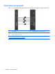
Front panel components Figure 1-1 HP t610 Thin Client (left) and HP t610 PLUS Thin Client (right) front panel components (1) Power button (4) Line-out (headphone) audio connector (2) Flash activity LED (5) Universal serial bus (USB) connectors (2) (3) Line-in (microphone) connector For more information, refer to the model-specific QuickSpecs at http://h18004.www1.hp.com/products/quickspecs/ QuickSpecs_Archives/QuickSpecs_Archives.html.
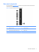
Rear panel components For more information, http://www.hp.com and search for your specific thin client model to find the model-specific QuickSpecs. Figure 1-2 HP t610 Thin Client rear panel components (1) DVI-I connector for DVI-D and VGA output (6) Serial connector (2) DisplayPort connector (7) PS/2 connectors (2) (3) Ethernet RJ-45 connector (8) Power cord retention slot (4) Universal serial bus (USB) connectors (2) 2.0 (9) Cable lock slot (5) Universal serial bus (USB) connectors (2) 3.
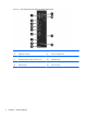
Figure 1-3 HP t610 PLUS Thin Client rear panel components 4 (1) DVI-I connector for DVI-D and VGA output (7) PS/2 connectors (2) (2) DisplayPort connector (8) Power cord retention slot (3) Ethernet RJ-45 connector (9) Cable lock slot (4) Universal serial bus (USB) connectors (2) 2.0 (10) Parallel connector (5) Universal serial bus (USB) connectors (2) 3.
Installing the rubber feet CAUTION: To prevent loss of performance or damage to the thin client, be sure to install the rubber feet before operating the thin client in a horizontal orientation. To install the rubber feet: 1. As you face the front of the thin client, lay the thin client on its left side. 2. Remove the feet from their backing. 3. Press each foot down securely onto a corner of the right side of the thin client.
Installing the stand If the thin client will be installed in an vertical orientation and it will not be mounted, the stand should be installed for stability. To install the stand: 1. Turn unit upside down. 2. Locate the slots on the bottom of the unit into which the tabs on the stand fit. 3. Insert the tabs into the slots, and then slide the stand about 1.26 cm (1/2 inch) toward the front of the unit until it locks into place.
Removing the stand To remove the stand: 1. Turn unit upside down. 2. Press the tab (1), and then slide the stand about 1.26 cm (1/2 inch) toward the back of the unit and lift the stand off the unit (2).
Using the power cord retention slot To prevent accidental disconnection, press a loop of the power cord into the power cord retention slot. Figure 1-7 Power cord retention slot (HP t610 PLUS Thin Client pictured in horizontal orientation) Serial number location Every thin client includes a unique serial number located as shown in the following illustration. Have this number available when contacting HP customer service for assistance.
2 Hardware changes General hardware installation sequence To ensure the proper installation thin client hardware components: 1. Back up any data, if necessary. 2. If the thin client is powered on: a. Turn the unit and any other attached devices off. b. Disconnect the power cord from the wall outlet. c. Disconnect any external devices or cables, such as a cable lock.
NOTE: Option kits include more detailed installation instructions. 7. Replace the side access panel and metal side cover. See Removing and replacing the side access panel and metal side cover on page 11 for more information. 8. Install the stand, if you will be using the thin client unmounted in a vertical orientation. See Installing the stand on page 6 for more information. 9. Reconnect any external devices and power cords. 10. Turn on the monitor, the thin client, and any devices you want to test.
Removing and replacing the side access panel and metal side cover Removing the side access panel WARNING! Before removing the side access panel, ensure that the thin client is turned off and the power cord is disconnected from the electrical outlet. To remove the left or right access panel: 1. Remove the stand, if it is installed. See Removing the stand on page 7 for more information. 2. Press the tab on the bottom cover (1), and then slide the cover back (2) and lift it off the chassis.
4. Slide the access panel about 6.35 mm (1/4 inch) toward the bottom of the unit, and then lift the access panel up and off the chassis. Figure 2-2 Removing the side access panel Removing the left metal side cover NOTE: Do not remove the metal side cover to install a SODIMM. The SODIMM compartment is in the right side of the chassis. You must remove the metal side cover to access internal components such as the battery or to install a flash memory module, internal hard drive, or PCI-Express card. 1.
2. Align the tabs on both sides of the cover and press the front edge down firmly until the latch closes. Figure 2-4 Replacing the metal side cover Replacing the side access panel To replace the access panel: 1. Place the access panel on the side of the unit, offset about 6.35 mm (1/4 inch) toward the top of the unit (1), allowing the hooks on the underside of the panel to slip into notches in the side access panel. 2. Slide the panel toward the bottom of the unit until it locks into place (2).
3. Turn the chassis upside down. Align the hooks on the underside of the bottom cover with the slots in the chassis and press the cover down and then forward until it locks in place. Figure 2-6 Replacing the bottom cover 4. 14 Replace the stand, if the thin client is to be used in the tower orientation.
Removing and replacing the battery Before beginning the replacement process, review General hardware installation sequence on page 9 for procedures you should follow before and after installing or replacing hardware. WARNING! You must remove the left side panel to access the battery. Before removing the side access panel, ensure that the thin client is turned off and the power cord is disconnected from the electrical outlet. To remove and replace the battery: 1. Locate the battery on the system board. 2.
Installing thin client options Various options can be installed on the thin client: ● Installing a SODIMM on page 16 ● Installing a flash memory module on page 19 ● Replacing an internal hard drive on page 21 ● Installing a PCI-Express card on page 24 ● Installing external drives on page 26 Installing a SODIMM The computer comes with double data rate 3 synchronous dynamic random access memory (DDR3SDRAM) small outline dual inline memory modules (SODIMMs).
CAUTION: You must disconnect the power cord and wait approximately 30 seconds for the power to drain before adding or removing memory modules. Regardless of the power-on state, voltage is always supplied to the memory modules as long as the computer is plugged into an active AC outlet. Adding or removing memory modules while voltage is present may cause irreparable damage to the memory modules or system board. The memory module sockets have gold-plated metal contacts.
4. Hold the SODIMM at approximately a 20-degree angle, and then press the SODIMM into the socket (1) until it is seated. Gently apply pressure to both the left and right edges of the SODIMM until the retention clips snap into place. NOTE: A SODIMM can be installed in only one way. Match the notch on the SODIMM with the tab on the socket. Figure 2-9 Installing a SODIMM 5. Press the SODIMM down into the compartment (2). 6.
7. Insert the tab on the front edge of the access plate into its slot (1) and press the plate down lightly to engage the latch (2). Figure 2-11 Replacing the SODIMM access plate 8. Slide the serial number tab back to its original position. Installing a flash memory module Before beginning the installation process, review General hardware installation sequence on page 9 for procedures you should follow before and after installing or replacing hardware.
2. Locate the correct flash memory module socket on the system board. a. The PATA socket (1) is populated by default. b. The SATA socket (2) can be populated with an optional SATA flash memory module. Figure 2-12 Identifying the Flash Memory Module sockets 3. Align the connector on the flash memory module with the socket on the system board and press the flash memory module into the socket. NOTE: A flash memory module can be installed in only one way.
4. Press the module connectors firmly into the flash memory module socket (1), making sure that the retention post on the system board is aligned with the hole in the module. Figure 2-14 Securing the flash memory module 5. Insert the screw provided in the flash memory module option kit through the hole in the module into the retention post (2) and tighten to secure the module.
2. Lift the drive bracket latch (1) and slide the drive bracket out of the retention bracket (2). Figure 2-15 Removing the hard drive bracket from the retention assembly 3. Remove the four screws that secure the hard drive in the drive bracket (1) and remove the hard drive from the bracket (2). Figure 2-16 Removing the hard drive from the drive bracket NOTE: Keep the four screws to use to install another hard drive. Installing an internal hard drive To install an internal hard drive: 1.
2. Insert the hard drive into the drive bracket (1) and secure it by fastening the four screws provided in the kit (2). Figure 2-17 Inserting the hard drive into the drive bracket 3. Locate the internal hard drive connector (1) and retention bracket (2) on the system board.
4. Align the screws on the side of the drive bracket with the slots inside the retention bracket and slide the drive bracket into the retention bracket (1). Figure 2-19 Securing the hard drive in the drive bracket 5. Press the drive bracket latch down firmly to push the drive onto the internal hard drive connector and secure the drive assembly (2). 6. Reinstall the PCIe card, if necessary. See Installing a PCI-Express card on page 24 for instructions.
To install a PCIe card: 1. Press down on the plastic blank tab and pull it out of the chassis. Figure 2-20 Removing the expansion slot blank 2. Open the metal latch securing the expansion slot cover on the inside of the thin client (1) and remove the expansion slot cover (2). Figure 2-21 Removing the expansion slot cover CAUTION: Do not lose this expansion slot cover.
3. Align the PCIe card connector with the PCI riser card socket and the expansion slot. Press the PCIe card firmly into the socket to ensure that the PCIe card is seated correctly and that the connector fits the expansion slot properly (1). Figure 2-22 Installing the PCIe card 4. Close the metal latch to secure the PCIe card (2). Installing external drives Various external USB drives are available as options for the t610 Series Thin Clients. For more information about these drives, visit http://h10010.
3 Mounting the thin client HP Quick Release The HP t610 Series Flexible Thin Clients incorporate four mounting points on one side of the unit. These mounting points follow the VESA (Video Electronics Standards Association) standard, which provides industry-standard mounting interfaces for Flat Displays (FDs), such as flat panel monitors, flat displays, and flat TVs. The HP Quick Release connects to the VESA-standard mounting points, allowing you to mount the thin client in a variety of orientations.
To use the HP Quick Release with a VESA-configured thin client: 1. Using four 15 mm screws included in the mounting device kit, attach one side of the HP Quick Release to the thin client as shown in the following illustration. Figure 3-2 Connecting the HP Quick Release to the thin client 2. Using four screws included in the mounting device kit, attach the other side of the HP Quick Release to the device to which you will mount the thin client. Make sure the release lever points upward.
3. Slide the side of the mounting device attached to the thin client (1) over the other side of the mounting device (2) on the device on which you want to mount the thin client. An audible 'click' indicates a secure connection. Figure 3-4 Connecting the thin client NOTE: When attached, the HP Quick Release automatically locks in position. You only need to slide the lever to one side to remove the thin client.
Supported mounting options The following illustrations demonstrate some of the supported mounting options for the mounting bracket. ● You can mount the thin client on the back of a flat panel monitor stand. Figure 3-5 Thin client mounted on back of monitor stand ● You can mount the thin client on a wall. Figure 3-6 Thin client mounted on wall ● 30 You can mount the thin client under a desk with at least one inch of clearance.
Figure 3-7 Thin client mounted under desk Supported mounting options 31
4 Computer Setup (F10) Utility, BIOS Settings Computer Setup (F10) Utilities Use Computer Setup (F10) Utility to do the following: 32 ● Change factory default settings. ● Set the system date and time. ● Set, view, change, or verify the system configuration, including settings for processor, graphics, memory, audio, storage, communications, and input devices. ● Modify the boot order of bootable devices such as hard drives, optical drives, or USB flash media devices.
Using Computer Setup (F10) Utilities Computer Setup can be accessed only by turning the computer on or restarting the system. To access the Computer Setup Utilities menu, complete the following steps: 1. Turn on or restart the computer. 2. Press either Esc or F10 while the “Press the ESC key for Startup Menu” message is displayed at the bottom of the screen. Pressing Esc displays a menu that allows you to access different options available at startup.
Table 4-2 Computer Setup—File Option Description System Information Lists: ● Product name ● SKU number (some models) ● Processor type/speed/stepping ● Cache size (L1/L2) ● Installed memory size/speed, number of channels (single or dual) (if applicable) ● Integrated MAC address for embedded, enabled NIC (if applicable) ● System BIOS (includes family name and version) ● Chassis serial number ● Asset tracking number About Displays copyright notice.
Table 4-3 Computer Setup—Storage (continued) Device Configuration Lists all installed BIOS-controlled storage devices. When a device is selected, detailed information and options are displayed. The following options may be presented: Hard Disk: Size, model, firmware version, serial number, connector color. ● SMART (ATA disks only) ● SSD Life Used ● Translation mode (ATA disks only) Lets you select the translation mode to be used for the device.
Table 4-3 Computer Setup—Storage (continued) Storage Options SATA Emulation CAUTION: SATA emulation changes may prevent access to existing hard drive data and degrade or corrupt established volumes. Allows you to choose how the SATA controller and devices are accessed by the operating system. There are two supported options: IDE (default) and AHCI. IDE (default option) - This is the most backwards-compatible setting of the three options.
Table 4-4 Computer Setup—Security (continued) Power-On Password Allows you to set and enable a power-on password. The power-on password prompt appears after a power cycle or reboot. If the user does not enter the correct power-on password, the unit will not boot. Password Options Allows you to enable/disable: (This selection appears only if a power-on password or setup password is set.
Table 4-4 Computer Setup—Security (continued) System IDs Master Boot Record Security Allows you to set: ● Asset tag (18-byte identifier), a property identification number assigned by the company to the computer. ● Ownership tag (80-byte identifier) displayed during POST. ● Universal Unique Identifier (UUID) number. The UUID can only be updated if the current chassis serial number is invalid. (These ID numbers are normally set in the factory and are used to uniquely identify the system.
Table 4-4 Computer Setup—Security (continued) System Security (some models: these options are hardware dependent) Data Execution Prevention (enable/disable) - Helps prevent operating system security breaches. Default is enabled. SVM CPU Virtualization (enable/disable). Controls the virtualization features of the processor. Changing this setting requires turning the computer off and then back on. Default is disabled.
Computer Setup—Power NOTE: Support for specific Computer Setup options may vary depending on the hardware configuration. Table 4-5 Computer Setup—Power Option Description OS Power Management ● Idle Power Savings—Extended/Auto/Normal. Allows certain operating systems to decrease the processors power consumption when the processor is idle. Default is extended. ● Runtime Power Management— Enable/Disable.
Computer Setup—Advanced NOTE: Support for specific Computer Setup options may vary depending on the hardware configuration. Table 4-6 Computer Setup—Advanced (for advanced users) Option Heading Power-On Options Allows you to set: ● POST mode (QuickBoot, Clear Memory, FullBoot, or FullBoot Every x Days). ● POST messages (enable/disable). Default is disabled. ● Press the ESC key for Startup Menu (Enable/Disable). Controls display of the message at the bottom of the POST screen during boot.
Table 4-6 Computer Setup—Advanced (for advanced users) (continued) Bus Options Device Options On some models, allows you to enable or disable: ● PCI SERR# Generation. Default is enabled. ● PCI VGA Palette Snooping, which sets the VGA palette snooping bit in PCI configuration space; only needed when more than one graphics controller is installed. Default is disabled. Allows you to set: ● Printer mode (Bi-Directional, EPP + ECP, Output Only). Default is EPP+ECP. ● Num Lock State at Power-On (off/on).
Changing BIOS Settings from the REPSETUP utility Some BIOS settings may be changed locally within the operating system without having to go through the F10 utility1. This table identifies the items that can be controlled with this method.
44 SATA1 Device available Device hidden SATA2 Device available Device hidden Network Service Boot Disable Enable Enter Ownership Tag na na Enter UUID na na Data Execution Prevention Disable Enable SVM CPU Virtualization Disable Enable Activate Embedded Security On Next Boot Disable Enable Embedded Security Activation Policy F1 to Boot Allow user to reject, No Prompts OS management of Embedded Security Device Disable Enable Reset of Embedded Security Device through OS Disable
POST Delay (in seconds) None 5, 10, 15, 20 Bypass F1 Prompt on Configuration Changes Disable Enable Sunday – Saturday Disable Enable BIOS Power-On Time (hh:mm) 00:00 na PCI SERR# Generation Enable Disable PCI VGA Palette Snooping Disable Enable Printer Mode EPP+ECP Bi-Directional, Output-Only Num Lock State at Power-On Off On Integrated Video Auto Disable, Force UMA Size 512M 32M, 64M, 256M, 512M, 1G Internal Speaker Enable Disable NIC Option ROM Download PXE Disable Seri
5 Diagnostics and Troubleshooting LEDs Table 5-1 Power and IDE Flash Activity LEDs LED Status Power LED Off When the unit is plugged into the wall socket and the Power LED is off, the unit is powered off. However, the network can trigger a Wake On LAN event in order to perform management functions. Power LED On Displays during boot sequence and while the unit is on.
Wake-on LAN Wake-on LAN (WOL) allows a computer to be turned on or resumed from sleep or hibernation state by a network message. You can enable or disable WOL in Computer Setup using the S5 Maximum Power Savings setting. To enable or disable WOL: 1. Turn on or restart the computer. 2. Press either Esc or F10 while the “Press the ESC key for Startup Menu” message is displayed at the bottom of the screen.
Resetting the Administrator and power-on passwords You can reset the Administrator and power-on passwords as follows: 1. Turn off the computer and disconnect the power cord from the power outlet. 2. Remove the side access panel and the metal side cover. 3. Remove the password jumper from the system board header labeled PSWD. 4. Replace the metal side cover and the side access panel. 5. Connect the computer to AC power, and then turn on the computer. 6.
Interpreting POST Diagnostic Front Panel LEDs and Audible Codes This section covers the front panel LED codes as well as the audible codes that may occur before or during POST that do not necessarily have an error code or text message associated with them. WARNING! When the computer is plugged into an AC power source, voltage is always applied to the system board.
Table 5-3 Diagnostic Front Panel LEDs and Audible Codes (continued) Activity Beeps Possible Cause Recommended Action Red Power LED flashes five times, once every second, followed by a two second pause. Beeps stop after fifth iteration but LEDs continue until problem is solved. 5 Pre-video memory error. CAUTION: To avoid damage to the memory modules or the system board, you must unplug the computer power cord before attempting to reseat, install, or remove a memory module.
POST Numeric Codes and Text Messages This section covers those POST errors that have numeric codes associated with them. The section also includes some text messages that may be encountered during POST. NOTE: The computer will beep once after a POST text message is displayed on the screen. Table 5-4 Numeric Codes and Text Messages Control panel message Description Recommended action 103-System Board Failure DMA or timers. 1. Clear CMOS. 2. Remove expansion boards. 3. Replace the system board.
Table 5-4 Numeric Codes and Text Messages (continued) Control panel message Description Recommended action 301-Keyboard Error Keyboard failure. 1. Reconnect keyboard with computer turned off. 2. Check connector for bent or missing pins. 3. Ensure that none of the keys are depressed. 4. Replace keyboard. 510-Flash Screen Image Corrupted Flash Screen image has errors. Reflash the system ROM with the latest BIOS image.
Troubleshooting Basic Troubleshooting If the thin client is experiencing operating problems or will not power on, review the following items. Table 5-5 Power-On Troubleshooting Issue Procedures The thin client unit is experiencing operating problems. Ensure that the following connectors are securely plugged into the thin client unit: The thin client unit does not power on. The thin client unit powers on and displays a splash screen, but does not connect to the server.
Table 5-5 Power-On Troubleshooting (continued) A newly connected unknown USB peripheral does not respond or USB peripherals connected prior to the newly connected USB peripheral will not complete their device actions. An unknown USB peripheral may be connected and disconnected to a running platform as long as you do not reboot the system. If problems occur, disconnect the unknown USB peripheral and reboot the platform. Video does not display. 1.
If you are running in a Linux environment go to step 3. 2. If you are running in a Microsoft RIS PXE environment press the F12 key to activate the network service boot as soon as the DHCP IP information appears on the screen. If the unit does not boot to the network the server is not configured to PXE. If you missed the F12 cue, the system will try to boot to the ATA flash that is not present. The message on the screen will read: ERROR: Non-system disk or disk error. Replace and press any key when ready.
6 Restoring the Flash Image System Requirements To create a recovery device for the purpose of reflashing or restoring the software image on the ROM, you will need the following: ● A personal computer running Microsoft Windows XP Professional, Windows Vista, or Windows 7. ● One or more HP t610 Series Thin Clients ● 4-GB USB flash device for Microsoft Windows Embedded Standard 2009 (WES) (if using the USB format) or Linux. This restore method will not work with all USB flash devices.
Formatting a USB Flash Drive CAUTION: To prevent loss of data, be sure that you have saved any user-created data from the USB drive to another drive. 1. Connect your USB flash device (drive key) to your personal computer. Ensure that only one USB flash device is connected to the system. 2. Click USB Format. 3. Select the USB drive from the list, using the up and down arrows to display the correct drive letter.
A Specifications Table A-1 HP t610 Thin Client Dimensions Width (front to back) 220 mm 8.7 in. Height (top to bottom, without stand) 240 mm 9.4 in Depth (side to side) 40 mm 1.6 in. Approximate Weight (without stand) 1.49 kg 3.29 lb 10° to 40° C 50° to 104° F -30° to 60° C -22° to 140° F Temperature Range (fanless design)* Operating** (max. rate of change is 10° C per hour or 18° F per hour) Nonoperating (max.
Table A-1 HP t610 Thin Client (continued) Power Supply Operating Input Voltage Range 100–240 VAC 100–240 VAC Rated Line Frequency 50–60 Hz 50–60 Hz Power Output (maximum) 65 W 65 W Width (front to back) 220 mm 8.7 in. Height (top to bottom, without stand) 240 mm 9.4 in Depth (side to side) 65 mm 2.6 in. Approximate Weight (without stand) 1.98 kg 4.
Table A-2 HP t610 PLUS Thin Client (continued) Power Supply 60 Operating Input Voltage Range 100–240 VAC 100–240 VAC Rated Line Frequency 50–60 Hz 50–60 Hz Power Output (maximum) 85 W 85 W Appendix A Specifications
B Adding an Image Restore Tool 1. Ensure that the boot order is set to use the Network as the first boot device. 2. Ensure that IBR.exe (Image Restore) and Flash.dd are stored in the same directory on the server. (e.g., c:\program files\altiris\express\deployment server\images) 3. From the Altiris Deployment Server Console, click File > New > Job . 4. Enter a unique name for the job that you will use to deploy the original thin client image. 5. Click the name of the new job. 6.
C Configuring a PXE Server Prerequisites NOTE: This Troubleshooting section is not intended to enable HP Service to support PXE software. All PXE software is supported by authorized service providers on a warranty or service contract basis. Customers that call the HP Customer Service Center with PXE issues and questions should be referred to their PXE provider for assistance. Additionally, refer to the following: – For Windows 2000: http://support.microsoft.
Authorizing Remote Installation Services (RIS PXE Server) If you have installed RIS on a server other than the server running DHCP, authorize PXE with DHCP as follows: 1. Record the IP address of the RIS PXE Server. 2. Log on to the DHCP Server as administrator. 3. From the Control Panel, double-click Administrative Tools. 4. Double-click DHCP. 5. Right-click DHCP (just above the domain name) and select Manage Authorized Servers. 6. Click Authorize. 7.
4. Click Delegate Control. 5. Click Next. 6. Click Add to add users. 7. Highlight Everyone and click Add. 8. Click OK. 9. Click Next. 10. Select Join a Computer to the Domain. 11. Click Next. 12. Click Finish. RIS Menu 1. Install the RIS menu of your choice. 2. Configure the RIS menu. 3. Refer to the help file provided by the RIS menu for instructions on creating a network bootable diskette and RIS menu for PXE.
D System BIOS Updating or restoring a BIOS Windows BIOS Flashing You can use the BIOS Flash Update SoftPaq to restore or upgrade the system BIOS. Several methods for changing the BIOS firmware stored on your computer are available . HPQFlash.exe is a utility designed to flash the System BIOS within a Microsoft Windows environment. To display the available options for this utility, type [Path]\HPQFlash -? at a command prompt or local search box.
the DOS Flash folder to the USB device, boot the computer from the USB device, and execute the DOSFlash application. To see a more complete description of the DOS flash utilities, view DOSFlash.txt located in the DOS Flash folder of the SoftPaq. This folder also contains the required binary image of the BIOS. The binary image file is named xxx_MMmm.bin where "xxx" is the BIOS family, "MM" is the major version number, and "mm" is the minor version number.
BootBlock Emergency Recovery Mode In the event of a failed BIOS update (for example if power is lost while updating), the System BIOS may become corrupted. BootBlock Emergency Recovery Mode detects this condition and automatically searches the root directory of the hard drive and any USB media sources for a compatible binary image. Copy the binary (.bin) file in the DOS Flash folder to the root of the desired storage device, and then power on the system.
E Electrostatic discharge A discharge of static electricity from a finger or other conductor may damage system boards or other static-sensitive devices. This type of damage may reduce the life expectancy of the device. Preventing electrostatic damage To prevent electrostatic damage, observe the following precautions: ● Avoid hand contact by transporting and storing products in static-safe containers.
Index A access panel removing 11 replacing 13 adding an image restore tool 61 altitude specifications 58, 59 audible codes 49 authorizing Remote Installation Services 63 B basic troubleshooting 53 battery, replacing 15 beep codes 49 BIOS 65 updating 65 C cautions HP Quick Release 29 static electricity 9 changing BIOS settings in the REPSETUP utility 43 components front panel 2 rear panel 3 configuring a PXE server 62 configuring Remote Installation Services 63 D diagnostics and troubleshooting 46 dimension
O options 16 installing 9 supported 9 P PCIe card, HP t610 PLUS Thin Client 24 PCIe card, installing 24 power and IDE flash activity LEDs 46 power button location 2 power connector location 3 power cord retention slot 8 power LED location 2 power output specifications 59, 60 power supply specifications 59, 60 power-on diagnostic tests 48 power-on sequence 47 preventing electrostatic damage 68 PS/2 connectors location 3 PXE 57, 62 R rear panel components 3 HP t610 PLUS Thin Client 4 HP t610 Thin Client 3 rel