
Hardware Reference Manual


Table Of Contents
- Product Features
- Hardware Upgrades
- Serviceability Features
- Warnings and Cautions
- Using the Small Form Factor Computer in a Tower Orientation
- Unlocking the Smart Cover Lock
- Removing the Computer Access Panel
- Replacing the Computer Access Panel
- Removing the Front Bezel
- Removing Bezel Blanks
- Replacing the Front Bezel
- Installing Additional Memory
- Removing or Installing an Expansion Card
- Drive Positions
- Installing and Removing Drives
- System Board Drive Connections
- Removing an Optical Drive
- Installing an Optical Drive into the 5.25-inch Drive Bay
- Removing an External 3.5-inch Drive
- Installing a Drive into the 3.5-inch External Drive Bay
- Removing and Replacing the Primary 3.5-inch Internal SATA Hard Drive
- Removing and Replacing a Removable 3.5-inch SATA Hard Drive
- Specifications
- Battery Replacement
- External Security Devices
- Electrostatic Discharge
- Computer Operating Guidelines, Routine Care and Shipping Preparation
- Index
Installing and Removing Drives
When installing additional drives, follow these guidelines:
●
The primary Serial ATA (SATA) hard drive must be connected to the dark blue primary SATA
connector on the system board labeled SATA0.
●
Connect a SATA optical drive to the white SATA connector on the system board labeled SATA1.
●
Connect a second SATA hard drive to the next available (unpopulated) SATA connector on the
system board by following the numbered sequence of the connectors.
●
Always populate the dark blue SATA0 and white SATA1 connectors before the light blue SATA4
connector.
●
Connect a diskette drive to the connector labeled FLOPPY.
●
Connect a media card reader to the USB connector labeled MEDIA.
●
The system does not support Parallel ATA (PATA) optical drives or PATA hard drives.
●
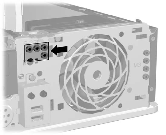
You must install guide screws to ensure the drive will line up correctly in the drive cage and lock
in place. HP has provided extra guide screws for the external drive bays (four 6-32 standard screws
and four M3 metric screws), installed in the front of the chassis, under the front bezel. The 6-32
standard screws are required for a secondary hard drive. All other drives (except the primary hard
drive) use M3 metric screws. The HP-supplied metric screws are black and the HP-supplied
standard screws are silver. If you are replacing the primary hard drive, you must remove the four
silver and blue 6-32 isolation mounting guide screws from the old hard drive and install them in the
new hard drive.
Figure 2-19 Secondary Hard Drive 6-32 Guide Screws Location
Figure 2-20 Extra Optical Drive M3 Guide Screws Location
ENWW Installing and Removing Drives 27