
Hardware Reference Manual


Table Of Contents
- Product Features
- Hardware Upgrades
- Serviceability Features
- Warnings and Cautions
- Using the Small Form Factor Computer in a Tower Orientation
- Unlocking the Smart Cover Lock
- Removing the Computer Access Panel
- Replacing the Computer Access Panel
- Removing the Front Bezel
- Removing Bezel Blanks
- Replacing the Front Bezel
- Installing Additional Memory
- Removing or Installing an Expansion Card
- Drive Positions
- Installing and Removing Drives
- System Board Drive Connections
- Removing an Optical Drive
- Installing an Optical Drive into the 5.25-inch Drive Bay
- Removing an External 3.5-inch Drive
- Installing a Drive into the 3.5-inch External Drive Bay
- Removing and Replacing the Primary 3.5-inch Internal SATA Hard Drive
- Removing and Replacing a Removable 3.5-inch SATA Hard Drive
- Specifications
- Battery Replacement
- External Security Devices
- Electrostatic Discharge
- Computer Operating Guidelines, Routine Care and Shipping Preparation
- Index
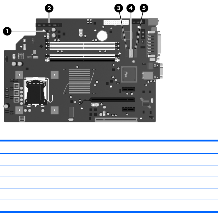
System Board Drive Connections
Refer to the following illustration and table to identify the system board drive connectors.
Figure 2-21 System Board Drive Connections
Table 2-4 System Board Drive Connections
No. System Board Connector System Board Label Color
1 Media Card Reader MEDIA black
2 Diskette Drive FLOPPY black
3 SATA0 SATA0 dark blue
4 SATA1 SATA1 white
5 SATA4 SATA4 light blue
ENWW Installing and Removing Drives 29