HP ProLiant DL380 G6 Carrier-Grade Server Read Before Install Carrier-Grade Instructions HP Part Number: AM275-9001A Published: July 2012 Edition: 3
© Copyright 2009, 2012 Hewlett-Packard Development Company, L. P. The information contained herein is subject to change without notice. The only warranties for HP products and services are set forth in the express warranty statements accompanying such products and services. Nothing herein should be construed as constituting an additional warranty. HP shall not be liable for technical or editorial errors or omissions contained herein. NEBS™ is a trademark of Telecordia Technologies Incorporated.
1 Converting to carrier-grade This document provides information for the carrier-grade version of the commercial HP ProLiant DL380 G6 Server. This chapter provides the steps required to convert the commercial HP ProLiant DL380 G6 Server to its carrier-grade version.
Converting to carrier-grade
2 Cabling Installing the ground lug To meet the bonding and grounding criteria for NEBS compliance, a dedicated ground lug is required. To install the ground lug, see the steps illustrated in the following figure: 1 2 3 Star washers Grounding lug (545155-001) T15 Torx screw (192308-002) The following figure illustrates the finished assembly of the ground lug.
Cable information This section provides cabling information for installing the HP ProLiant DL380 G6 Carrier-Grade Server. NEBS chassis ground This carrier-grade product is intended for use in both common bonding networks and isolated bonding networks. The product is equipped with a NEBS-compliant chassis ground lug located on the rear of the product. The ground lug included with the product accepts wire gauges between 10 and 12 AWG.
3 Power supplies specifications and cable information HP 1200W PSU 48VDC Input Part Number 437573-B21 Input Voltage Range (DCV) 36-72 Frequency Range (Nominal) (Hz) DC Nominal Input Voltage (VDC) 36 48 72 1200 1200 1200 38 28 19 Maximum Rated Input Wattage Rating (Watts) 1380 1350 1365 Maximum Rated VA (Volt-Amp) 1380 1350 1365 87 89 88 Power Factor N/A N/A N/A Leakage Current (mA) N/A N/A N/A 20 25 35 1 1 3 4713 4610 4662 Maximum Rated Output Wattage Nominal Inpu
Nominal Input Current (A rms) 9.7 9.0 7.0 6.8 6.4 9.1 5.9 Maximum Rated Input Wattage Rating (Watts) 930 1034 1348 1348 1348 1348 1348 Maximum Rated VA (Volt-Amp) 970 1079 1406 1406 1406 1406 1406 Efficiency (%) of Maximum Rated Output Wattage 86 87 89 89 89 89 89 Power Factor 0.97 0.97 0.97 0.97 0.97 0.97 0.97 Leakage Current (mA) 0.42 0.50 0.83 0.87 0.92 0.96 1.
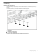
4 Installing the fans WARNING! To prevent personal injury from hazardous energy, remove watches, rings, or other metal objects. 1. 2. 3. 4. Power off the server. Remove power to the server. Remove the top cover. Locate the fan blanks. 5. 6. Remove and discard the fan blanks. Install the fans into the board. Make sure the power connector on the fan lines up with the power connector on the board. 7. Replace the top cover.
5. Change the #10 system maintenance switch setting to the On position. You can use a plastic ball-point pen to flip the system maintenance switch. 6. Replace the top cover. Verifying the system maintenance switch setting After you switch the setting, verify that the #10 system maintenance switch is in the On position. NOTE: The following instructions use iLO 2. For complete information and instructions on using iLO 2, see the HP Integrated Lights-Out 2 User Guide on the HP website at http://www.hp.
3. Select the Temperatures tab. If the temperature thresholds appear as shown below, the switch is set correctly. Incorrect thresholds If the thresholds don't show up correctly, you might have switched the wrong switch. Ensure the switch is reset to the factory defaults as described in the HP ProLiant DL380 G6 Maintenance and Service Guide on the HP website at http://h20000.www2.hp.com/bizsupport/TechSupport.
5 Installing the DL380 server into a seismic rack For information on the installation of the DL380 using the commercial rack mount kit, see the HP website at http://www.hp.com/support/manuals. Under Servers, click ProLiant ml/dl and tc series servers, and select your product. While not specifically designed for use in seismic rack solutions, the commercial kit was successfully evaluated in the AH343A HP Seismic Rack to the NEBS Zone 4 criteria as part of the DL380 Server NEBS certification.
NOTE: The square-hole cage nuts that are provided in the rack kit do not fit in the round holes in the seismic rack. 3. 4. Install the round-hole M5 cage nuts in the appropriate rack hole positions where you want to install the DL380 Server. • Two cage nuts on the front of each rail. • Two cage nuts on the back of each rail. Line up the mounting rail with the cage nuts, and fasten the mounting rail to the rack with M5 screws.
NOTE: 5. Apply some pressure when fastening the screws to the mounting rail. Repeat steps 1 through 3 for the other mounting rail. WARNING! To reduce the risk of personal injury or equipment damage, be sure that the rack is adequately stabilized before sliding the inner slides into the slide mounting bracket assemblies. 6. 7. 14 To install the side rails on each side of the server, align each side rail to the server, and snap it into place. Slide the server onto the mounting rails and into the rack.
8. 9. Snap the server into place. Fasten the server to the rack, using the screws included in the rack kit as described in the rack kit instructions for preparing a server for shipment. a. Pull down the plastic retention lever on each side of the server. b. Insert the screws into each side. 10. Install the cable arm using the instructions in the rack kit.
*AM275-9001A* Printed in the US