Maintenance and Service Guide HP ProDesk 600 G3 Small Form Factor
© Copyright 2017 HP Development Company, L.P. AMD is a trademark of Advanced Micro Devices, Inc. Bluetooth is a trademark owned by its proprietor and used by HP Inc. under license. Intel, Celeron, and Pentium are trademarks of Intel Corporation in the U.S. and other countries. Microsoft and Windows are trademarks of the Microsoft group of companies. The information contained herein is subject to change without notice.
About This Book WARNING! Text set off in this manner indicates that failure to follow directions could result in bodily harm or loss of life. CAUTION: Text set off in this manner indicates that failure to follow directions could result in damage to equipment or loss of information. NOTE: Text set off in this manner provides important supplemental information.
iv About This Book
Table of contents 1 Product features ........................................................................................................................................... 1 Standard configuration features ........................................................................................................................... 1 Front panel components ........................................................................................................................................
SATA hard drives .................................................................................................................................................. 18 SATA hard drive cables ......................................................................................................................................... 19 SATA data cable ................................................................................................................................. 19 SMART ATA drives ...............
Computer Setup–Main ....................................................................................................................... 65 Computer Setup—Security ............................................................................................................... 67 Computer Setup—Advanced ............................................................................................................. 69 Computer Setup—UEFI Drivers .................................................................
Creating recovery media and backups ............................................................................................ 118 Creating HP Recovery media (select products only) .................................................... 118 Using Windows tools ....................................................................................................................... 119 Restore and recovery ...........................................................................................................
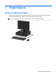
1 Product features Standard configuration features Features may vary depending on the model. For support assistance and to learn more about the hardware and software installed on your computer model, run the HP Support Assistant utility. NOTE: This computer model can be used in a tower orientation or a desktop orientation.
Front panel components Drive configuration may vary by model. Some models have a bezel blank covering the slim optical drive bay. Front panel components 1 Slim optical drive (optional) 6 USB 2.0 port with HP Sleep and Charge 2 SD card reader (optional) 7 Audio-out (headphone)/Audio-in (microphone) combo jack 3 USB Type-C charging port 8 Hard drive activity light 4 USB 3.x ports (2) 9 Power button 5 USB 2.0 port NOTE: The light on the power button is normally white when the power is on.
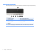
Rear panel components Refer to the following images and tables for the rear components on vPro and non-vPro systems. vPro systems Rear panel components 1 Audio-in jack 6 Optional port (DisplayPort, HDMI, VGA or USB-C) (USB-C option has alt mode DisplayPort or 15W output) 2 Optional serial port 7 USB 2.0 ports (2) 3 RJ-45 (network) jack 8 USB 3.
Non-vPro systems Rear panel components 1 Audio-in jack 6 Optional port 2 Optional port 7 USB 2.0 ports (4) 3 RJ-45 (network) jack 8 USB 3.x ports (2) 4 Audio-out jack for powered audio devices 9 Power cord connector 5 DisplayPort monitor connectors (2) NOTE: Your model may have additional optional ports available from HP. When a device is plugged into either audio jack, a dialog box will appear on the monitor screen asking if you want to use the jack for a microphone or a headphone.
2 Illustrated parts catalog Computer major components NOTE: HP continually improves and changes product parts. For complete and current information on supported parts for your computer, go to http://partsurfer.hp.com, select your country or region, and then follow the on-screen instructions.
Item Description 8 GB 4 GB * Processors (include replacement thermal material) Intel Core i7-7700 processor Intel Core i5-7600 processor Intel Core i5-7500 processor Intel Core i3-7320 processor Intel Core i3-7300 processor Intel Core i3-7100 processor Intel Core i7-6700 processor Intel Core i5-6600 processor Intel Core i5-6500 processor Intel Core i3-6100 processor Intel Pentium G4620 processor Intel Pentium G4600 processor Intel Pentium G4560 processor Intel Pentium G4400 processor Intel Celeron G3950
Misc parts Item Description (1) Speaker (2) Serial port assembly (3) HDMI option port (4) Fan duct (5) Optical drive bracket (6) Optical drive bezel * Chassis stand * Dust filter bezel * Antenna kit, WLAN * Hard drive conversion bracket, 2.5-inch to 3.5-inch * Card reader, USB 3.
Item Description * HP Business Security Lock Kit, v2 * HP Dual head keyed cable lock * HP keyed cable lock, 10 mm * HP master keyed cable lock, 10 mm Mouse * PS2, optical * USB, laser * USB, optical * Antimicrobial (People’s Republic of China only) * Washable * USB, grey * HP USB Hardened Keyboards * 8 * HP USB slim * HP antimicrobial * USB/PS2 Washable * Wireless keyboard, mouse, and receiver * PS/2 slim not illustrated Chapter 2 Illustrated parts catalog
Cables and adapters Item Description Cables (1) SATA drive power cable (2) SATA data cable with latch, 4.7 inch, 2 straight ends (3) SATA data cable, 5.7 inch, 2 straight ends * DisplayPort cable * DVI-DVI cable Adapters * * PCIe to M.2 adapter with full-sized bracket * DisplayPort to HDMI 1.4 * DisplayPort to VGA * DisplayPort to DVI * DVI to VGA * USB-C to DisplayPort * USB-C to USB 3.0 * PCIe to M.
Mass storage devices Description Hard drives 2-TB, 7200-rpm, 3.5-inch 1-TB, 7200-rpm, 3.5-inch 1-TB, 7200-rpm, 2.5-inch 1-TB, 7200-rpm,. hybrid SSD, 3.5-inch 1-TB, 5400-rpm,. hybrid SSD, 3.5-inch 500 GB, 7200 rpm, 3.5-inch 500 GB, 7200 rpm, 7 mm 500-GB, 7200-rpm, OPAL2, self-encrypting drive (SED) 500-GB, 5400-rpm, FIPS 500-GB, 5400-rpm, hybrid SSD Solid-state drives, 2280, 2.
Cards, boards, modules Description Nvidia GeForce GT730 2 GB PCIe x8, graphics card Nvidia GeForce GT720 1 GB PCIe x8, graphics card Intel PRO/1000 NIC, single port Option boards DisplayPort USB Type-C VGA Parallel port PS/2 + serial port USB 3.1 Type Cx1 PCIe x1 card WLAN modules Intel 8265 802.11AC 2x2 Wi-Fi +Bluetooth M.2 Combo Card non-VPro Intel 7265 802.11AC 2x2 Wi-Fi +Bluetooth M.2 Combo Card non-VPro Intel 3168 802.11AC 2x2 Wi-Fi +Bluetooth M.
3 Routine care, SATA drive guidelines, and disassembly preparation This chapter provides general service information for the computer. Adherence to the procedures and precautions described in this chapter is essential for proper service. CAUTION: When the computer is plugged into an AC power source, voltage is always applied to the system board. You must disconnect the power cord from the power source before opening the computer to prevent system board or component damage.
Generating static The following table shows that: ● Different activities generate different amounts of static electricity. ● Static electricity increases as humidity decreases.
● Heel straps/Toe straps/Boot straps can be used at standing workstations and are compatible with most types of shoes or boots. On conductive floors or dissipative floor mats, use them on both feet with a maximum of one-megohm ± 10% resistance between the operator and ground.
● Transparent metallized shielding bags ● Transparent shielding tubes Operating guidelines To prevent overheating and to help prolong the life of the computer: ● Keep the computer away from excessive moisture, direct sunlight, and extremes of heat and cold. ● Operate the computer on a sturdy, level surface. Leave a 10.2-cm (4-inch) clearance on all vented sides of the computer and above the monitor to permit the required airflow.
To clean the computer case, follow the procedures described below: ● To remove light stains or dirt, use plain water with a clean, lint-free cloth or swab. ● For stronger stains, use a mild dishwashing liquid diluted with water. Rinse well by wiping it with a cloth or swab dampened with clear water. ● For stubborn stains, use isopropyl (rubbing) alcohol. No rinsing is needed as the alcohol will evaporate quickly and not leave a residue.
Service considerations Listed below are some of the considerations that you should keep in mind during the disassembly and assembly of the computer. Power supply fan The power supply fan is a variable-speed fan based on the temperature in the power supply. CAUTION: The cooling fan is always on when the computer is in the “On” mode. The cooling fan is off when the computer is in “Standby,” “Suspend,” or “Off” modes.
● If a drive must be mailed, place the drive in a bubble-pack mailer or other suitable protective packaging and label the package “Fragile: Handle With Care.” ● Do not remove hard drives from the shipping package for storage. Keep hard drives in their protective packaging until they are actually mounted in the CPU. ● Avoid dropping drives from any height onto any surface. ● If you are inserting or removing a hard drive, turn off the computer.
SATA hard drive cables SATA data cable Always use an HP approved SATA 6.0 Gb/s cable as it is fully backwards compatible with the SATA 1.5 Gb/s drives. Current HP desktop products ship with SATA 6.0 Gb/s hard drives. SATA data cables are susceptible to damage if overflexed. Never crease a SATA data cable and never bend it tighter than a 30 mm (1.18 in) radius. The SATA data cable is a thin, 7-pin cable designed to transmit data for only a single drive.
4 Removal and replacement procedures: Small Form Factor Adherence to the procedures and precautions described in this chapter is essential for proper service. After completing all necessary removal and replacement procedures, run the Diagnostics utility to verify that all components operate properly. NOTE: Not all features listed in this guide are available on all computers.
Access panel 1. Prepare the computer for disassembly (Preparation for disassembly on page 20). 2. Slide the access panel release lever to the right (1) so that it locks into place. Then slide the access panel back (2) and lift it off the computer (3). To install the access panel, reverse the removal procedure.
Front bezel 1. Prepare the computer for disassembly (Preparation for disassembly on page 20). 2. Remove the access panel (Access panel on page 21). 3. Lift up the four tabs on the top of the bezel (1), and then rotate the bezel off the chassis (2). To install the front bezel, reverse the removal procedure.
Bezel blank On some models, a bezel blank covers the slim optical drive bay. Remove the bezel blank before installing an optical drive. To remove the bezel blank: 1. Prepare the computer for disassembly (Preparation for disassembly on page 20). 2. Remove the access panel (Access panel on page 21). 3. Remove the front bezel (Front bezel on page 22). 4. Then press inward on the tab on the left side of the blank (1), and then rotate the blank off the front bezel (2).
Front bezel dust filter (optional) Some models are equipped with an optional front bezel dust filter. You must periodically clean the dust filter so that the dust collected on the filter does not impede air flow through the computer. NOTE: The optional front bezel dust filter is available from HP. To remove, clean, and replace the dust filter: 24 1. Prepare the computer for disassembly (Preparation for disassembly on page 20). 2.
Drive cage You must remove the drive cage to access most computer components. 1. Prepare the computer for disassembly (Preparation for disassembly on page 20). 2. Remove the access panel (Access panel on page 21). 3. Disconnect the power and data cables from the rear of all drives in the drive cage. 4. To remove the drive cage, push the release lever on the left side of the cage inward (1), lift the left side of the cage up (2), and then slide the right side of the cage out of the chassis (3). 5.
Memory Description 16-GB, PC4-2400 8-GB, PC4-2400 4-GB, PC4-2400 2-GB, PC4-2400 The computer comes with double data rate 4 synchronous dynamic random access memory (DDR4-SDRAM) dual inline memory modules (DIMMs). The memory sockets on the system board are populated with at least one preinstalled memory module. To achieve the maximum memory support, you can populate the system board with up to 64 GB of memory configured in a high-performing dual-channel mode.
Populating DIMM sockets There are four memory sockets on the system board, with two sockets per channel. The sockets are labeled DIMM1, DIMM2, DIMM3, and DIMM4. Sockets DIMM1 and DIMM2 operate in memory channel B. Sockets DIMM3 and DIMM4 operate in memory channel A. The system will automatically operate in single-channel mode, dual-channel mode, or flex mode, depending on how the DIMMs are installed.
Installing memory modules CAUTION: You must disconnect the power cord and wait approximately 30 seconds for the power to drain before adding or removing memory modules. Regardless of the power-on state, voltage is always supplied to the memory modules as long as the computer is plugged into an active AC outlet. Adding or removing memory modules while voltage is present may cause irreparable damage to the memory modules or system board. The memory module sockets have gold-plated metal contacts.
Expansion card Description NVIDIA GT730 2 GB DDR3 PCIex8 graphics card NVIDIA GT730 1 GB DDR3 PCIex8 graphics card Intel PRO/1000 NIC Parallel (printer) port USB 3.1 Type Cx1 PCIe x1 card The computer has one PCI Express x4 expansion socket and one PCI Express x16 expansion socket. NOTE: The PCI Express sockets support only low profile cards. You can install a PCI Express x1, x4, x8, or x16 expansion card in the PCI Express x16 socket.
30 a. If you are installing an expansion card in a vacant socket, remove the appropriate expansion slot cover on the back of the chassis. Insert a flat-bladed screwdriver into the slots on the rear of expansion slot cover (1) and rock the slot cover back and forth (2) to break it free from the chassis. b. If you are removing a PCI Express x4 card, hold the card at each end and carefully rock it back and forth until the connectors pull free from the socket.
c. If you are removing a PCI Express x16 card, pull the retention arm on the back of the expansion socket away from the card (1) and carefully rock the card back and forth until the connectors pull free from the socket. Lift the card straight up (2), and then away from the inside of the chassis (3) to remove it. Be sure not to scrape the card against other components. 6. Store the removed card in anti-static packaging. 7.
9. Rotate the slot cover retention latch back in place to secure the expansion card. 10. Connect external cables to the installed card, if needed. Connect internal cables to the system board, if needed. 11. Reconfigure the computer, if necessary.
System board connections Refer to the following illustration and table to identify the system board connectors for your model.
Drives Description Hard drives 2-TB, 7200-rpm, 3.5-inch 1-TB, 7200-rpm, 3.5-inch 1-TB, 7200-rpm, 2.5-inch 1-TB, 7200-rpm,. hybrid SSD, 3.5-inch 1-TB, 5400-rpm,. hybrid SSD, 3.5-inch 500 GB, 7200 rpm, 3.5-inch 500 GB, 7200 rpm, 7 mm 500-GB, 7200-rpm, OPAL2, self-encrypting drive (SED) 500-GB, 5400-rpm, FIPS 500-GB, 5400-rpm, hybrid SSD Solid-state drives, 2280, 2.5-inch 512 GB, SED, OPAL 2, TLC 512-GB, FIPS-140-2 256 GB, SED, OPAL 2, TLC 256-GB, FIPS-140-2 256-GB 128-GB Solid-state drives, 2280, NVMe, M.
● The primary Serial ATA (SATA) hard drive must be connected to the dark blue primary SATA connector on the system board labeled SATA0. ● Connect an optical drive to the light blue SATA connector on the system board labeled SATA1. IMPORTANT: To prevent loss of work and damage to the computer or drive: If you are inserting or removing a drive, shut down the operating system properly, turn off the computer, and unplug the power cord. Do not remove a drive while the computer is on or in standby mode.
Removing a 9.5 mm slim optical drive CAUTION: All removable media should be taken out of a drive before removing the drive from the computer. 1. Prepare the computer for disassembly (Preparation for disassembly on page 20). 2. Remove the access panel (Access panel on page 21). 3. Disconnect the power cable (1) and data cable (2) from the rear of the optical drive. IMPORTANT: When removing the cables, pull the tab or connector instead of the cable itself to avoid damaging the cable. 4.
Installing a 9.5 mm slim optical drive 1. Prepare the computer for disassembly (Preparation for disassembly on page 20). 2. Remove the access panel (Access panel on page 21). 3. If you are installing a slim optical drive in a bay covered by a bezel blank, remove the front bezel and then remove the bezel blank. See Bezel blank on page 23 for more information. 4. Align the small pin on the release latch with the small hole on the side of the drive and press the latch firmly onto the drive. 5.
6. Connect the power cable (1) and data cable (2) to the rear of the drive. 7. Connect the opposite end of the data cable to the light blue SATA connector on the system board labeled SATA1. NOTE: Refer to System board connections on page 33 for an illustration of the system board drive connectors. Removing and replacing a 3.5-inch hard drive CAUTION: All removable media should be taken out of a drive before removing the drive from the computer. 1.
3. Pull the release lever next to the rear of the hard drive outward (1). While pulling the release lever out, slide the drive forward until it stops, and then lift the drive up and out of the bay (2). 4. Install mounting screws on the sides of the hard drive using standard 6-32 silver-and-blue mounting screws. NOTE: If replacing a 3.5-inch hard drive, transfer the mounting screws from the old hard drive to the new hard drive. You can purchase extra mounting screws from HP.
– 40 Secure the drive to the bay adapter bracket by installing four black M3 adapter bracket screws through the underside of the bracket and into the drive.
– 5. Install four 6-32 silver-and-blue mounting screws in the adapter bracket (two on each side of the bracket). Align the mounting screws with the slots on the chassis drive cage, press the hard drive down into the bay, and then slide the drive back until it stops and locks in place.
6. Connect the data cable (1) and power cable (2) to the rear of the hard drive. NOTE: The data cable for the primary hard drive must be connected to the dark blue connector on the system board labeled SATA0 to avoid any hard drive performance problems. Removing and installing an M.2 SSD storage card NOTE: 42 The computer supports 2230 and 2280 M.2 SSD cards. 1. Prepare the computer for disassembly (Preparation for disassembly on page 20). 2. Remove the access panel (Access panel on page 21). 3.
6. To install an M.2 SSD card, slide the pins on the card into the system board connector while holding the card at approximately a 30° angle (1). Press the other end of the card down (2), and then secure the card with the screw (3). 7. Replace the drive cage. 8. Reconnect the power and data cables to all drives in the drive cage and reassemble the computer.
Fan duct The fan duct sits between the fan sink and rear of the computer. 1. Prepare the computer for disassembly (Preparation for disassembly on page 20). 2. Remove the access panel (Access panel on page 21). 3. Remove the drive cage (Drive cage on page 25). 4. Remove the power cable from the clips at the top of the duct (1). 5. Pull the tabs away from each other (2), and then lift the fan duct out of the computer (3). To install the fan duct, reverse the removal procedures.
Fan sink The fan sink is secured atop the processor with four captive Torx screws. The fan sink includes a heat sink and a fan. 1. Prepare the computer for disassembly (Preparation for disassembly on page 20). 2. Remove the access panel (Access panel on page 21). 3. Remove the drive cage (Drive cage on page 25). 4. Disconnect the fan cable from the system board connector labeled CPUFAN (1). 5. Loosen the four captive Torx T15 screws (2) that secure the fan sink to the system board tray.
Processor Description Intel Core i7-7700 processor Intel Core i5-7600 processor Intel Core i5-7500 processor Intel Core i3-7320 processor Intel Core i3-7300 processor Intel Core i3-7100 processor Intel Core i7-6700 processor Intel Core i5-6600 processor Intel Core i5-6500 processor Intel Core i3-6100 processor Intel Pentium G4620 processor Intel Pentium G4600 processor Intel Pentium G4560 processor Intel Pentium G4400 processor Intel Celeron G3950 processor Intel Celeron G3930 processor Intel Celeron G3900
7. Lift the processor (3) straight up and remove it. CAUTION: Do NOT handle the pins in the processor socket. These pins are very fragile and handling them could cause irreparable damage. Once pins are damaged it may be necessary to replace the system board. The heat sink must be installed within 24 hours of installing the processor to prevent damage to the processor’s solder connections.
M.2 WLAN module Description Intel 8265 802.11AC 2x2 Wi-Fi +Bluetooth M.2 Combo Card non-VPro Intel 7265 802.11AC 2x2 Wi-Fi +Bluetooth M.2 Combo Card non-VPro Intel 3168 802.11AC 2x2 Wi-Fi +Bluetooth M.2 Combo Card non-VPro The WLAN module is secured with one screw and has two connected antennas. 1. Prepare the computer for disassembly (Preparation for disassembly on page 20). 2. Remove the access panel (Access panel on page 21). 3. Remove the drive cage (Drive cage on page 25). 4.
Power supply Description Power supply, 180W, 92% efficient Power supply, 180W, 85% efficient WARNING! To reduce potential safety issues, only the power supply provided with the computer, a replacement power supply provided by HP, or a power supply purchased as an accessory from HP should be used with the computer. The power supply is located at the rear of the chassis. It is held in place by three Torx screws outside of the chassis and a release lever inside of the chassis.
7. Slide the power supply forward (4), and then lift it out of the chassis. To install the power supply, reverse the removal procedure.
Drive power cable 1. Prepare the computer for disassembly (Preparation for disassembly on page 20). 2. Remove the access panel (Access panel on page 21). 3. Remove the drive cage (Drive cage on page 25). 4. Disconnect the cable from the system board connector labeled SATA PWR0. The following image illustrates the cable. To install the drive power cable, reverse the assembly procedures.
Speaker The speaker is attached to the front of the chassis under the rotating drive cage. 52 1. Prepare the computer for disassembly (Preparation for disassembly on page 20). 2. Remove the access panel (Access panel on page 21). 3. Remove the front bezel (Front bezel on page 22). 4. Remove the drive cage (Drive cage on page 25). 5. From the outside, front of the chassis, remove the Phillips screw that secures the speaker to the chassis. 6.
7. Remove the speaker cable from the clips built into the bottom of the chassis (1), and then remove the speaker from the computer (2). To install the speaker, reverse the removal procedures.
Serial port assembly A removable serial port can be installed on the back of the computer. To remove the serial port assembly: 1. Prepare the computer for disassembly (Preparation for disassembly on page 20). 2. Remove the access panel (Access panel on page 21). 3. Remove the drive cage (Drive cage on page 25). 4. From the outside of the chassis, remove the two nuts that secure the assembly to the rear of the computer. 5.
Option port A removable option port can be installed on the back of the computer. To remove the option port: 1. Prepare the computer for disassembly (Preparation for disassembly on page 20). 2. Remove the access panel (Access panel on page 21). 3. Remove the drive cage (Drive cage on page 25). 4. From the inside of the chassis, remove the two Phillips screws that secure the assembly to the system board (1). 5.
System board 56 1. Prepare the computer for disassembly (Preparation for disassembly on page 20). 2. Remove the access panel (Access panel on page 21). 3. Remove the drive cage (Drive cage on page 25). 4.
7. Remove the eight Torx screws that secure the system board to the chassis. 8. Lift the front of the system board upward (1), and the pull the system board away from and out of the computer (2). To install the system board, reverse the removal procedure. NOTE: When replacing the system board, you must also change the chassis serial number in the BIOS. CAUTION: When reconnecting the cables it is important that they be positioned correctly.
System board callouts 58 Sys Bd Label Color Component Sys Bd Label Color Component PWRCPU White 4-pin processor power PWR White 6-pin main power CPU Silver Processor SATA0 Dark blue Hard drive CPUFAN White Processor fan SATAPWR0 Black Drives DIMM1 White Memory module SATA1 Light blue Any SATA Device other than the primary hard drive DIMM2 Black Memory module PSWD Blue Clear system passwords DIMM3 White Memory module BATTERY Black RTC battery DIMM4 Black Memory m
Antennas 1. Prepare the computer for disassembly (Preparation for disassembly on page 20). 2. Remove the access panel (Access panel on page 21). 3. Remove the front bezel (Front bezel on page 22). 4. Remove the drive cage (Drive cage on page 25). 5. Disconnect the antennas from the WLAN module (M.2 WLAN module on page 48). 6. On the front of the computer, remove the Torx screw that secures the antenna to the computer. 7.
8. Inside of the computer, remove the antenna cables that route along the sides of the computer. 9. Inside of the computer, remove the antenna cables that route along the sides of the computer. 10. On the inside, rear of the computer, remove the antenna cable by routing it though the hole in the computer.
11. On the inside, front of the computer, remove the antenna cable by routing it though the hole in the computer. To install the antennas, reverse the removal procedures.
Desktop to tower orientation The Small Form Factor computer can be used in a tower orientation with an optional tower stand that can be purchased from HP. NOTE: To stabilize the computer in a tower orientation, HP recommends the use of the optional tower stand. 1. Remove/disengage any security devices that prohibit moving the computer. 2. Remove all removable media, such as compact discs or USB flash drives, from the computer. 3.
5 Computer Setup (F10) Utility Computer Setup (F10) Utilities Use Computer Setup (F10) Utility to do the following: ● Change settings from the defaults or restore the settings to default values. ● View the system configuration, including settings for processor, graphics, memory, audio, storage, communications, and input devices. ● Modify the boot order of bootable devices such as hard drives, optical drives, or USB flash media devices.
4. Use the arrow (left and right) keys to select the appropriate heading. Use the arrow (up and down) keys to select the option you want, then press Enter. To return to the Computer Setup Utilities menu, press Esc. 5. To apply and save changes, select Main > Save Changes and Exit. ● If you have made changes that you do not want applied, select Ignore Changes and Exit. ● To restore settings from the Advanced and Main menus to original values, select Apply Factory Defaults and Exit.
Computer Setup–Main NOTE: Support for specific Computer Setup options may vary depending on the hardware configuration. Table 5-1 Computer Setup—Main Option Description System Information Lists all information in following list if Advanced System Information is selected. Lists smaller subset if Basic System Information is selected.
Table 5-1 Computer Setup—Main (continued) Update System BIOS ● Hardware subsystem tests ● Component tests ● Show test logs ● Language selection Lets you update the system BIOS from www.hp.com or another network server, from a removable USB drive, or from a file located on the hard drive. Displays current BIOS version information. ● ‘Check HP.com for BIOS Updates’ or ‘Check the Network for BIOS Updates’ The string that appears here depends on the setting in ‘BIOS Update Preferences’.
Table 5-1 Computer Setup—Main (continued) Apply Factory Defaults and Exit Restores the factory system configuration settings to the computer after rebooting. Does not apply to options in the Security menu. Ignore Changes and Exit Exits Computer Setup without applying or saving any changes. Save Changes and Exit Saves changes to current system configuration, exits Computer Setup, and reboots. Suppress POST Errors Select to suppress most system messages during POST (Power-On Self Test).
Table 5-2 Computer Setup—Security (continued) Displays the current TPM version. ● TPM Device Lets you set the Trusted Platform Module as available or hidden. ● TPM State Select to enable the TPM. ● ClearTPM Select to reset the TPM to an unowned state. After the TPM is cleared, it is also turned off. To temporarily suspend TPM operations, turn the TPM off instead of clearing it. CAUTION: Clearing the TPM resets it to factory defaults and turns it off.
Table 5-2 Computer Setup—Security (continued) After you select a drive, the following options are available: Set DriveLock Master Password. Sets the drive’s master password but does not enable DriveLock. Enable DriveLock. Sets the drive’s user password and enables DriveLock. ● Secure Erase Lets you select a hard drive to completely erase.
Table 5-3 Computer Setup—Advanced (for advanced users) (continued) ● UEFI Boot Order. Default is enabled. Specify the order in which UEFI boot sources (such as a internal hard drive, USB hard drive, USB optical drive, or internal optical drive) are checked for a bootable operating system image. UEFI boot sources always have precedence over legacy boot sources.
Table 5-3 Computer Setup—Advanced (for advanced users) (continued) M.2 WLAN/BT Lets you disable the wireless module slot. Default is enabled. M.2 SSD Lets you disable the M.2 solid-state drive slot. Default is enabled. Allow PCIe/PCI SERR# Interrupt (enable/disable) Allows PCI devices to report PCI/PCIe System Error signals, such as address parity errors, data parity errors, and critical errors other than parity. Default is enabled.
Table 5-3 Computer Setup—Advanced (for advanced users) (continued) Enables USB charging port capability when the system is in hibernate or shutdown state. ● Front USB Type-C Downstream Charging Enables USB charging port capability when the system is in hibernate or shutdown state. Restrict USB Devices Specify the following categories of USB devices to enable: ● Allow all USB devices (default) ● Allow only keyboard and mouse ● Allow all but storage devices and hubs.
Table 5-3 Computer Setup—Advanced (for advanced users) (continued) S4 (Hibernation)= 4 blinks at 1Hz (50% duty cycle) followed by a pause of 2 seconds (white LED) — repeated cycles of 4 blinks and a pause. S5 (Soft Off) = LED is off. Power On from Keyboard Ports (enable/disable) When enabled, this feature allows a key press to power on the system when it is off (S5 state). If using a USB keyboard, it must be plugged into one of the rear ports labeled with the keyboard icon. Default is disabled.
Recovering the Configuration Settings This method of recovery requires that you first perform the Save to Removable Media command with the Computer Setup (F10) Utility before Restore is needed. (See Computer Setup–Main on page 65 in the Computer Setup—File table.) The Save to Removable Media option creates a file named HPSETUP.TXT on an inserted USB flash media device. This file can be edited to change the settings on Restore. An asterisk (*) marks the selected option for a setting.
6 Troubleshooting without diagnostics This chapter provides information on how to identify and correct minor problems, such as USB devices, hard drive, optical drive, graphics, audio, memory, and software problems. If you encounter problems with the computer, refer to the tables in this chapter for probable causes and recommended solutions.
If it becomes necessary to call for technical assistance, be prepared to do the following to ensure that your service call is handled properly: ● Be in front of your computer when you call. ● Write down the computer serial number, product ID number, and monitor serial number before calling. ● Spend time troubleshooting the problem with the service technician. ● Remove any hardware that was recently added to your system. ● Remove any software that was recently installed.
● If you have installed an operating system other than the factory-installed operating system, check to be sure that it is supported on the system. ● If the system has multiple video sources (embedded, PCI, or PCI-Express adapters) installed (embedded video on some models only) and a single monitor, the monitor must be plugged into the monitor connector on the source selected as the primary VGA adapter.
Computer date and time display is incorrect. Cause Solution RTC (real-time clock) battery may need to be replaced. Reset the date and time under Control Panel (Computer Setup can also be used to update the RTC date and time). If the problem persists, replace the RTC battery. See the Removal and Replacement section for instructions on installing a new battery, or contact an authorized dealer or reseller for RTC battery replacement.
Poor performance. Cause Solution Low on memory. Add more memory. Hard drive fragmented. Defragment hard drive. Program previously accessed did not release reserved memory back to the system. Restart the computer. Virus resident on the hard drive. Run virus protection program. Too many applications running. 1. Close unnecessary applications to free up memory. 2. Add more memory. 3.
System does not power on and the LEDs on the front of the computer are not flashing. Cause Solution System unable to power on. Press and hold the power button for less than 4 seconds. If the hard drive LED turns white, then: 1. If equipped with a voltage selector, check that the voltage selector (located on the rear of the power supply) is set to the appropriate voltage. Proper voltage setting depends on your region. 2.
Solving power problems Common causes and solutions for power problems are listed in the following table. Power supply shuts down intermittently. Cause Solution If equipped with a voltage selector, voltage selector switch on rear of computer chassis (some models) not switched to correct line voltage (115V or 230V). Select the proper AC voltage using the selector switch. Power supply will not turn on because of internal power supply fault. Replace the power supply.
Solving hard drive problems Hard drive error occurs. Cause Solution Hard disk has bad sectors or has failed. 1. In Windows 7, click Start, click Computer, and right-click on a drive. Select Properties, and then select the Tools tab. Under Error-checking click Check Now. In Windows 10, type file in the taskbar search box, and then select File Explorer from the list of applications. In the left column, expand This PC, right-click on a drive, select Properties, and then select the Tools tab.
Nonsystem disk/NTLDR missing message. Cause Solution The system is trying to start from the hard drive but the hard drive may have been damaged. ▲ Perform Drive Protection System (DPS) testing in system ROM. System files missing or not properly installed. 1. Insert bootable media and restart the computer. 2. Boot to the windows installation media and select the recovery option. If only a restore kit is available, then select the File Backup Program option, and then restore the system. 3.
Solving media card reader problems Media card will not work in a digital camera after formatting it in Windows. Cause Solution By default, Windows will format any media card with a capacity greater than 32MB with the FAT32 format. Some digital cameras use the FAT (FAT16 & FAT12) format and can not operate with a FAT32 formatted card. Either format the media card in the digital camera or select FAT file system to format the media card in a computer with Windows.
After installing the media card reader and booting to Windows, the reader and the inserted cards are not recognized by the computer. Cause Solution The operating system needs time to recognize the device if the reader was just installed into the computer and you are turning the PC on for the first time. Wait a few seconds so that the operating system can recognize the reader and the available ports, and then recognize the media inserted in the reader.
Blank screen (no video). Cause Solution To access Control Panel in Windows 7, click Start, and then select Control Panel. To access Control Panel in Windows 10, type control panel in the taskbar search box, and then select Control Panel from the list of applications. 2. Monitor is configured to use an input that is not active. Expand the Resolution box, and then use the sliding control to reset the resolution.
Monitor does not function properly when used with energy saver features. Cause Solution Monitor without energy saver capabilities is being used with energy saver features enabled. Disable monitor energy saver feature. Dim characters. Cause Solution The brightness and contrast controls are not set properly. Adjust the monitor brightness and contrast controls. Cables are not properly connected.
“No Connection, Check Signal Cable” displays on screen. Cause Solution Monitor video cable is disconnected. Connect the video cable between the monitor and computer. CAUTION: Ensure that the computer power is off while connecting the video cable. “Out of Range” displays on screen. Cause Solution Video resolution and refresh rate are set higher than what the monitor supports. Restart the computer and enter Safe Mode.
Fuzzy focus; streaking, ghosting, or shadowing effects; horizontal scrolling lines; faint vertical bars; or unable to center the picture on the screen (flat panel monitors using an analog VGA input connection only). Cause Solution with the synchronization, go to the following Web site, select the appropriate monitor, and download either SP32347 or SP32202: http://www.hp.com/support Graphics card is not seated properly or is bad (some models). 1. Reseat the graphics card. 2. Replace the graphics card.
Sound does not come out of the speaker or headphones. Cause Solution Audio is hidden in Computer Setup. Enable the audio in Computer Setup: Advanced > Built-in Device Options. The external speakers are not turned on. Turn on the external speakers. The audio device may be connected to the wrong jack. Ensure that the device is connected to the correct jack on the computer. The rear audio jack output is the green receptacle.
Line-in jack is not functioning properly. Cause Solution Jack has been reconfigured in the audio driver or application software. In the audio driver or application software, reconfigure the jack or set the jack to its default value. There is no sound or sound volume is too low. Cause Solution The application is set to use a different audio device than speakers. Some graphics cards support audio over the DisplayPort connection (if applicable), so multiple audio devices may be listed in Device Manager.
Printer will not turn on. Cause Solution The cables may not be connected properly. Reconnect all cables and check the power cord and electrical outlet. Printer prints garbled information. Cause Solution The correct printer driver for the application is not installed. Install the correct printer driver for the application. The cables may not be connected properly. Reconnect all cables. Printer memory may be overloaded. Reset the printer by turning it off for one minute, then turn it back on.
Keyboard commands and typing are not recognized by the computer. Cause Solution CAUTION: When attempting to resume from Sleep date, do not hold down the power button for more than four seconds. Otherwise, the computer will shut down and you will lose any unsaved data. Mouse does not respond to movement or is too slow. Cause Solution Mouse connector is not properly plugged into the back of the computer. Shut down the computer using the keyboard. Windows 7: 1.
Solving Hardware Installation Problems You may need to reconfigure the computer when you add or remove hardware, such as an additional drive or expansion card. If you install a plug and play device, Windows automatically recognizes the device and configures the computer. If you install a non-plug and play device, you must reconfigure the computer after completing installation of the new hardware. In Windows, use the Add Hardware Wizard and follow the instructions that appear on the screen.
Computer will not start. Cause Solution 2. Observe the beeps and LED lights on the front of the computer. Beeps and flashing LEDs are codes for specific problems. 3. If you still cannot resolve the issue, contact Customer Support. Power LED flashes Red three times and then white two times. Cause Solution Memory is installed incorrectly or is bad.
Network status link light never flashes. NOTE: The network status light is supposed to flash when there is network activity. Cause Solution No active network is detected. Check cabling and network equipment for proper connection. Network controller is not set up properly. Check for the device status within Windows, such as Device Manager for driver load and the Network Connections applet within Windows for link status.
Table 6-2 Solving Network Problems (continued) Diagnostics passes, but the computer does not communicate with the network. Cause Solution To access Control Panel in Windows 7, click Start, and then select Control Panel. To access Control Panel in Windows 10, type control panel in the taskbar search box, and then select Control Panel from the list of applications. Network controller stopped working when an expansion board was added to the computer. Cause Solution The network controller requires drivers.
System setup utility reports unprogrammed EEPROM. Cause Solution Unprogrammed EEPROM. Contact an authorized service provider. Solving memory problems If you encounter memory problems, some common causes and solutions are listed in the following table. CAUTION: Power may still be supplied to the DIMMs when the computer is turned off (depending on the Management Engine (ME) settings).
Insufficient memory error during operation. Cause Solution Too many Terminate and Stay Resident programs (TSRs) are installed. Delete any TSRs that you do not need. You have run out of memory for the application. Check the memory requirements for the application or add more memory to the computer. Power LED flashes Red five times, once every second, followed by a two second pause, and the computer beeps five times. (Beeps stop after fifth iteration but LEDs continue flashing.
Drive not found (identified). Cause Solution If this is a newly installed drive, run the Computer Setup utility and try adding a POST delay under Advanced > Power-On Options. The device is attached to a SATA port that has been hidden in Computer Setup. Run the Computer Setup utility and ensure Device Available is selected for the device's SATA port in Advanced > Port Options. Drive responds slowly immediately after power-up. Run Computer Setup and increase the POST Delay in Advanced > Power-On Options.
CD-ROM, CD-RW, DVD-ROM, or DVD-R/RW drive cannot read a disc or takes too long to start. Cause Solution CD or DVD disc is dirty. Clean CD or DVD with a CD cleaning kit, available from most computer stores. Windows does not detect the CD-ROM or DVD-ROM drive. 1. Use Device Manager to remove or uninstall the device. To access Device Manager in Windows 7, click Start, select Control Panel, and then select Device Manager.
System will not boot from USB flash drive. Cause Solution Boot order is not correct. Run the Computer Setup utility and change boot sequence in Advanced > Boot Options. Removable Media Boot is disabled in the Computer Setup utility. Run the Computer Setup utility and enable booting to removable media in Advanced > Boot Options. Ensure USB is enabled in Storage > Boot Order. The computer boots to DOS after making a bootable flash drive. Cause Solution Flash drive is bootable.
Solving front panel component problems If you encounter problems with devices connected to the front panel, refer to the common causes and solutions listed in the following table. A USB device, headphone, or microphone is not recognized by the computer. Cause Solution Device is not properly connected. 1. Turn off the computer. 2. Reconnect the device to the front of the computer and restart the computer. The device does not have power.
Unable to connect to the Internet. Cause Solution 3. In the Browsing history section on the General tab, click the Delete button. 4. Select the Cookies check box and click the Delete button. Windows 10: 1. Type control panel in the taskbar search box, and then select Control Panel from the list of applications. 2. Click Internet Options. 3. In the Browsing history section, click the Delete button. 4. Select the Cookies and website data check box and click the Delete button.
Solving software problems Most software problems occur as a result of the following: ● The application was not installed or configured correctly. ● There is insufficient memory available to run the application. ● There is a conflict between applications. ● Be sure that all the needed device drivers have been installed. ● If you have installed an operating system other than the factory-installed operating system, check to be sure it is supported on the system.
7 POST error messages and diagnostic front panel LEDs and audible codes This appendix lists the error codes, error messages, and the various indicator light and audible sequences that you may encounter during Power-On Self-Test (POST) or computer restart, the probable source of the problem, and steps you can take to resolve the error condition. POST Message Disabled suppresses most system messages during POST, such as memory count and nonerror text messages.
Control panel message 008–Microcode Patch Error 009–PMM Allocation Error during MEBx Download Description Recommended action RTC (real-time clock) battery may need to be replaced. problem persists, replace the RTC battery. See the Removal and Replacement section for instructions on installing a new battery. Processor is not supported by the BIOS. 1. Upgrade BIOS to proper version. 2. Change the processor. 1. Reboot the computer. 2.
Control panel message Description Recommended action 00E-Inventory Error during MEBx Execution BIOS information passed to the MEBx resulted in a failure. 1. Reboot the computer. 2. If the error persists, update to the latest BIOS version. 3. If the error still persists, replace the system board. 1. Reboot the computer. 2. If the error persists, update to the latest BIOS version. 3. If the error still persists, replace the system board.
Control panel message 302-Hard Disk 2: SMART Hard Drive Detects Imminent Failure 309 – 30C: Hard Disk 3–6: SMART Hard Drive Detects Imminent Failure Description Recommended action Hard drive is about to fail. (Some hard drives have a hard drive firmware patch that will fix an erroneous error message.) Hard drive is about to fail. (Some hard drives have a hard drive firmware patch that will fix an erroneous error message.) 2. Apply hard drive firmware patch if applicable. (Available at http://www.hp.
Control panel message Description Recommended action 403-Serial Port D Address Conflict Detected Both external and internal serial ports are assigned to the same resources. 1. Remove any serial port expansion cards. 2. Clear CMOS. (See Password security and resetting CMOS on page 113.) 3. Reconfigure card resources and/or run Computer Setup or Windows utilities. If a PCI expansion card was recently added, remove it to see if the problem remains.
Control panel message Description Recommended action 904-SATA Cabling Error One or more SATA devices are improperly attached. For optimal performance, the SATA 0 and SATA 1 ports should be used for hard drives before other ports. Ensure SATA connectors are used in ascending order. For one device, use SATA 0. For two devices, use SATA 0 and SATA 1. For three devices, use SATA 0, SATA 1, and SATA 2. 90B-Fan Failure The system has detected that a cooling fan is not operating correctly. 1. Reseat fan.
2 BIOS 3 Hardware 4 Thermal 5 System board Patterns of blink/beep codes are determined by using the following parameters: ● 1 second pause occurs after the last major blink. ● 2 second pause occurs after the last minor blink. ● Beep error code sequences occur for the first 5 iterations of the pattern and then stop. ● Blink error code sequences continue until the computer is unplugged or the power button is pressed.
8 Password security and resetting CMOS This computer supports security password features, which can be established through the Computer Setup Utilities menu. This computer supports two security password features that are established through the Computer Setup Utilities menu: administrator password and power-on password. When you establish only an administrator password, any user can access all the information on the computer except Computer Setup.
1. Shut down the operating system properly, then turn off the computer and any external devices, and disconnect the power cord from the power outlet. 2. With the power cord disconnected, press the power button again to drain the system of any residual power. WARNING! To reduce the risk of personal injury from electrical shock and/or hot surfaces, be sure to disconnect the power cord from the wall outlet, and allow the internal system components to cool before touching.
Clearing and resetting the BIOS The CMOS button resets BIOS settings to default, but does not clear the passwords or affect any of the other Security settings. On Intel systems with advanced manageability features, the CMOS button will also partially unprovision AMT. 1. Turn off the computer and any external devices, and disconnect the power cord from the power outlet. 2. Disconnect the keyboard, monitor, and any other external equipment connected to the computer.
9 Using HP PC Hardware Diagnostics (UEFI) HP PC Hardware Diagnostics is a Unified Extensible Firmware Interface (UEFI) that allows you to run diagnostic tests to determine whether the computer hardware is functioning properly. The tool runs outside the operating system so that it can isolate hardware failures from issues that are caused by the operating system or other software components.
3. Enter the product name or number. – or – Select Identify now to let HP automatically detect your product. 4. Select your computer, and then select your operating system. 5. In the Diagnostic section, follow the on-screen instructions to select and download the UEFI version you want.
10 Backing up, restoring, and recovering Backing up, restoring, and recovering in Windows 10 This chapter provides information about the following processes. The information in the chapter is standard procedure for most products. ● Creating recovery media and backups ● Restoring and recovering your system For additional information, refer to the HP support assistant app. ▲ Type support in the taskbar search box, and then select the HP Support Assistant app.
You can use Windows tools to create system restore points and create backups of personal information, see Using Windows tools on page 119. ● If your computer does list the Recovery partition and the Windows partition, you can use HP Recovery Manager to create recovery media after you successfully set up the computer. HP Recovery media can be used to perform system recovery if the hard drive becomes corrupted.
Restore and recovery There are several options for recovering your system. Choose the method that best matches your situation and level of expertise: IMPORTANT: ● Windows offers several options for restoring from backup, refreshing the computer, and resetting the computer to its original state. For more information see the Get started app. ▲ ● Not all methods are available on all products. Select the Start button, and then select the Get started app.
IMPORTANT: HP Recovery Manager does not automatically provide backups of your personal data. Before beginning recovery, back up any personal data you want to retain. Using HP Recovery media, you can choose from one of the following recovery options: NOTE: Only the options available for your computer display when you start the recovery process. ● System Recovery—Reinstalls the original operating system, and then configures the settings for the programs that were installed at the factory.
Changing the computer boot order If your computer does not restart in HP Recovery Manager, you can change the computer boot order, which is the order of devices listed in BIOS where the computer looks for startup information. You can change the selection to an optical drive or a USB flash drive. To change the boot order: IMPORTANT: For a tablet with a detachable keyboard, connect the keyboard to the keyboard dock before beginning these steps. 1. Insert the HP Recovery media. 2.
Removing the HP Recovery partition (select products only) HP Recovery Manager software allows you to remove the HP Recovery partition to free up hard drive space. IMPORTANT: After you remove the HP Recovery partition, you will not be able to perform System Recovery or create HP recovery media from the HP Recovery partition. So before you remove the Recovery partition, create HP Recovery media; see Creating HP Recovery media (select products only) on page 118.
Guidelines ● When creating recovery media or backing up to discs, use any of the following types of discs (purchased separately): DVD+R, DVD+R DL, DVD-R, DVD-R DL, or DVD±RW. The discs you use will depend on the type of optical drive you are using. ● Be sure that the computer is connected to AC power before you start the recovery media creation process or the backup process.
● Store personal files in the Documents library, and back it up regularly. ● Back up templates that are stored in their associated directories. ● Save customized settings that appear in a window, toolbar, or menu bar by taking a screen shot of your settings. The screen shot can be a time-saver if you have to reset your preferences. ● When backing up to discs, number each disc after removing it from the drive.
To recover information you previously backed up: 1. Select Start, select All Programs, select Maintenance, and then select Backup and Restore. 2. Follow the on-screen instructions to recover your system settings, your computer (select products only), or your files. To recover your information using Startup Repair, follow these steps: CAUTION: Some Startup Repair options will completely erase and reformat the hard drive.
Using Windows 7 operating system media If you cannot use the recovery media you previously created using the HP Recovery Disc Creator (select products only), you must purchase a Windows 7 operating system DVD to reboot the computer and repair the operating system. To order a Windows 7 operating system DVD, go to the HP website. For U.S. support, go to http://www.hp.com/support. For worldwide support, go to http://welcome.hp.com/country/us/en/ wwcontact_us.html. You can also order the DVD by calling support.
A Battery replacement The battery that comes with the computer provides power to the real-time clock. When replacing the battery, use a battery equivalent to the battery originally installed in the computer. The computer comes with a 3-volt lithium coin cell battery. WARNING! The computer contains an internal lithium manganese dioxide battery. There is a risk of fire and burns if the battery is not handled properly. To reduce the risk of personal injury: Do not attempt to recharge the battery.
b. Slide the replacement battery into position, positive side up. The battery holder automatically secures the battery in the proper position. Type 2 a. To release the battery from its holder, squeeze the metal clamp that extends above one edge of the battery. When the battery pops up, lift it out (1). b. To insert the new battery, slide one edge of the replacement battery under the holder’s lip with the positive side up.
b. Insert the new battery and position the clip back into place. NOTE: After the battery has been replaced, use the following steps to complete this procedure. 8. Replace the access panel. 9. Plug in the computer and turn on power to the computer. 10. Reset the date and time, your passwords, and any special system setups using Computer Setup. 11. Lock any security devices that were disengaged when the access panel was removed.
B Statement of memory volatility The purpose of this chapter is to provide general information regarding nonvolatile memory in HP Business computers. This chapter also provides general instructions for restoring nonvolatile memory that can contain personal data after the system has been powered off and the hard drive has been removed. HP Business computer products that use Intel®-based or AMD®-based system boards contain volatile DDR memory.
g. If a DriveLock password is set, select the Security menu, and scroll down to Hard Drive Utilities under the Utilities menu. Select Hard Drive Utilities, select DriveLock, then uncheck the checkbox for DriveLock password on restart. Select OK to proceed. h. Select the Main menu, and then select Reset BIOS Security to factory default. Click Yes at the warning message. The computer will reboot. i.
Nonvolatile memory usage Nonvolatile Memory Type HP Sure Start flash (select models only) Amount (Size) Does this memory store customer data? Does this memory retain data when power is removed? 8 MBytes No Yes What is the purpose of this memory? Provides protected backup of critical System BIOS code, EC firmware, and critical computer configuration data for select platforms that support HP Sure Start.
Nonvolatile Memory Type Amount (Size) Does this memory store customer data? Does this memory retain data when power is removed? What is the purpose of this memory? How is data input into this memory? How is this memory write-protected? product, and then follow the on-screen instructions. Intel Management 1.5 MBytes or 7 Engine Firmware MBytes (present only in select Elite or Z models. For more information, go to http://www.hp.com/ support.
Questions and answers 1. How can the BIOS settings be restored (returned to factory settings)? IMPORTANT: Restore defaults does not securely erase any data on your hard drive. See question and answer 6 for steps to securely erase data. Restore defaults does not reset the Custom Secure Boot keys. See question and answer 7 for information about resetting the keys. 2. a.
IMPORTANT: Resetting will result in the loss of information. These steps will not reset Custom Secure Boot Keys. See question and answer 7 for information about resetting the keys. 7. a. Turn on or restart the computer, and then press esc while the “Press the ESC key for Startup Menu” message is displayed at the bottom of the screen. b. Select Main, and then select Reset Security to Factory Defaults. c. Follow the on-screen instructions. d.
C Power cord set requirements The power supplies on some computers have external power switches. The voltage select switch feature on the computer permits it to operate from any line voltage between 100-120 or 220-240 volts AC. Power supplies on those computers that do not have external power switches are equipped with internal switches that sense the incoming voltage and automatically switch to the proper voltage.
Country-specific requirements Additional requirements specific to a country are shown in parentheses and explained below. Country Accrediting Agency Country Accrediting Agency Australia (1) EANSW Italy (1) IMQ Austria (1) OVE Japan (3) METI Belgium (1) CEBC Norway (1) NEMKO Canada (2) CSA Sweden (1) SEMKO Denmark (1) DEMKO Switzerland (1) SEV Finland (1) SETI United Kingdom (1) BSI France (1) UTE United States (2) UL Germany (1) VDE 1.
D Specifications Chassis (in the desktop position) Height 3.74 in 95 mm Width 10.63 in 270 mm Depth 11.65 in 296 mm Approximate Weight 9.92 lb 4.5 kg Weight Supported (maximum distributed load in desktop position) 77 lb 35 kg Operating 50° to 95°F 10° to 35°C Nonoperating -22° to 140°F -30° to 60°C Temperature Range NOTE: Operating temperature is derated 1.0° C per 300 m (1000 ft) to 3000 m (10,000 ft) above sea level; no direct sustained sunlight. Maximum rate of change is 10° C/Hr.
Index A access panel illustrated 5 locked 78 removal and replacement 21 administrator password 113 audible codes 111 audio problems 89 B backup and recovery, Windows 7 123 Backup and Restore 125 backups creating 124 recovering 125 battery disposal 18 battery replacement 128 beep codes 111 BIOS clearing and resetting 115 boot order changing 122 booting options Full Boot 106 Quick Boot 106 C cable management 19 cable pinouts, SATA data 19 cautions AC power 12 cables 17 cooling fan 17 electrostatic discharge 1
dust filter 24 expansion card 29 M.2 SSD card 42 memory 26 primary 3.5-inch hard drive 38 slim optical drive 37 Internet access problems 103 K keyboard cleaning 16 keyboard problems 92 M M.
screws, correct size 17 serial number location 4 serial port assembly removal and replacement 54 serial port, illustrated 7 service considerations 17 software problems 105 servicing computer 17 solid-state drives sizes 10, 34 speaker illustrated 7 removal and replacement 52 specifications computer 139 Startup Repair, using 125 static electricity 13 supported discs, recovery 119 system board illustrated 5 removal and replacement 56 SATA connectors 18 system board connections 33 system memory, removing person