
HP Pavilion G6 Notebook PC - Maintenance and Service Guide
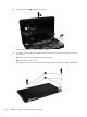
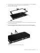
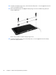
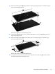
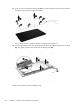
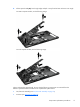
Table Of Contents
- Product description
- External component identification
- Illustrated parts catalog
- Removal and replacement procedures
- Specifications
- Setup Utility (BIOS)
- Backup and recovery
- Power cord set requirements
- Recycling
- Index
6.
Lift the display panel (4) straight up to remove it.
Reverse this procedure to install the display assembly.
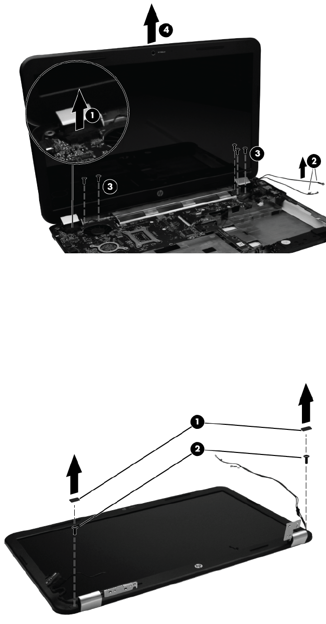
7.
To replace any of the display assembly internal components, remove the following screw covers
and screws:
(1) Two screw covers on the display bezel bottom edge
(2) Two Phillips 4.0 x 2.5 screws
The display screw covers are included in the Display Rubber Kit, spare part number 640882-001.
64 Chapter 4 Removal and replacement procedures