Maintenance and Service Guide HP ProDesk 400 G2 Small Form Factor
© Copyright 2014 Hewlett-Packard Development Company, L.P. The information contained herein is subject to change without notice. Microsoft and Windows are U.S. registered trademarks of the Microsoft group of companies. The only warranties for HP products and services are set forth in the express warranty statements accompanying such products and services. Nothing herein should be construed as constituting an additional warranty.
About This Book WARNING! Text set off in this manner indicates that failure to follow directions could result in bodily harm or loss of life. CAUTION: Text set off in this manner indicates that failure to follow directions could result in damage to equipment or loss of information. NOTE: Text set off in this manner provides important supplemental information.
iv About This Book
Table of contents 1 Product features ........................................................................................................................................... 1 Standard configuration features ........................................................................................................................... 1 Front panel components .......................................................................................................................................
SATA data cable ................................................................................................................................. 18 SMART ATA drives ................................................................................................................................................ 18 Cable management ..............................................................................................................................................
Computer Setup—Security ............................................................................................................... 65 Computer Setup—Power .................................................................................................................. 68 Computer Setup—Advanced ............................................................................................................ 69 Recovering the Configuration Settings ............................................................
10 System backup and recovery .................................................................................................................... 120 Backing up, restoring, and recovering in Windows 8.1 or Windows 8 ............................................................. 120 Creating recovery media and backups ........................................................................................... 120 Restoring and recovering using Windows tools ....................................................
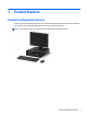
1 Product features Standard configuration features Features may vary depending on the model. For a complete listing of the hardware and software installed in the computer, run the diagnostic utility (included on some computer models only). NOTE: This computer model can be used in a tower orientation or a desktop orientation.
Front panel components Drive configuration may vary by model. Some models have a bezel blank covering one or more drive bays. 1 Slim Optical Drive (optional) 5 Headphone Connector 2 USB 2.0 Ports (black) 6 Dual-State Power Button 3 USB 3.0 Ports (blue) 7 Hard Drive Activity Light 4 Microphone Connector 8 3.5-inch Media Card Reader (optional) NOTE: The Power On Light is normally white when the power is on.
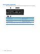
Rear panel components 1 PS/2 Mouse Connector (green) 6 Power Cord Connector 2 RJ-45 Network Connector 7 PS/2 Keyboard Connector (purple) 3 Serial Connector 8 DisplayPort Monitor Connector 4 USB 2.0 Ports (black) 9 VGA Monitor Connector 5 Line-In Audio Connector (blue) 10 Line-Out Connector for powered audio devices (green) NOTE: An optional second serial port and an optional parallel port are available from HP.
Serial number location Each computer has a unique serial number and a product ID number that are located on the exterior of the computer. Keep these numbers available for use when contacting customer service for assistance.
2 Illustrated parts catalog Computer major components This chapter provides part information for all chassis.
Item Description (4) System board (includes replacement thermal material) For use in models without Windows 8 For use in models with Windows 8 Standard For use in models with Windows 8 Professional For use in models with NetClone (the People’s Republic of China only) Memory modules (PC3,12800, CL11) 8-GB 4-GB 2-GB Processors (include replacement thermal material) Intel Core i7 4790 (3.6-GHz, 8-MB L3 cache), 84W Intel Core i7 4790s (3.2-GHz, 8-MB L3 cache), 65W Intel Core i7 4771 (3.
Item Description Intel Pentium G3450 (3.4-GHz, 3-MB L3 cache), 54W Intel Pentium G3440 (3.3-GHz, 3-MB L3 cache), 54W Intel Pentium G3430 (3.3-GHz, 3-MB L3 cache), 54W Intel Pentium G3420 (3.2-GHz, 3-MB L3 cache), 54W Intel Pentium G3250 (3.2-GHz, 3-MB L3 cache), 53W Intel Pentium G3240 (3.1-GHz, 3-MB L3 cache), 54W Intel Pentium G3220 (3.0-GHz, 3-MB L3 cache), 54W Intel Celeron G1850 (2.9-GHz, 2-MB L3 cache) Intel Celeron G1840 (2.
Misc parts Item Description (1) Fan sink (includes replacement thermal material) (2) Speaker (3) Printer port, PCI card (4) Fan duct (5) Serial port, PCI card Card reader, 14-in-1, USB 3.0, 3.5-inch Card reader, 15-in-1, USB 3.0, 3.5-inch, UHS-II Adapter, USB 3.0 to 2.0 Optical drive bezel blank Grommet, hard drive HP Ultraslim Keyed Cable Lock Clamp lock, universal cable, without plate Chassis stand Hard drive carrier, 2.5-inch to 3.
Item Description Mouse PS2, optical USB, HP Elite Washable HP USB Antimicrobial USB, optical Keyboard PS/2 USB Wireless, HP Elite with USB dongle (for use only in Brazil) Unbranded USB, unbranded, Katydid Smart card, CCID Wireless keyboard, mouse, and dongle kit (for use in all countries except for Brazil) Washable HP USB Antimicrobial Drives Description Hard drive 2 TB, 7200 rpm, 3.5 inch 1 TB, 10000 rpm 1 TB, 7200 rpm, 3.5 inch 1 TB hard drive, hybrid SSD 500 GB, 10000 rpm 500 GB, 7200 rpm, 2.
Description 128-GB Solid-state Drive (SSD), self-encrypting (SED) 120-GB Solid-state Drive (SSD), MLC 32-GB Solid-state Drive (SSD), 2.5 inch, MLC Optical drive Blu-ray BD-RW SuperMulti XL Drive DVD±RW drive DVD-ROM drive NOTE: 2.5-inch solid-state drives require an adapter for installation.
3 Routine care, SATA drive guidelines, and disassembly preparation This chapter provides general service information for the computer. Adherence to the procedures and precautions described in this chapter is essential for proper service. CAUTION: When the computer is plugged into an AC power source, voltage is always applied to the system board. You must disconnect the power cord from the power source before opening the computer to prevent system board or component damage.
Generating static The following table shows that: ● Different activities generate different amounts of static electricity. ● Static electricity increases as humidity decreases.
● Heel straps/Toe straps/Boot straps can be used at standing workstations and are compatible with most types of shoes or boots. On conductive floors or dissipative floor mats, use them on both feet with a maximum of one-megohm ± 10% resistance between the operator and ground.
● Transparent metallized shielding bags ● Transparent shielding tubes Operating guidelines To prevent overheating and to help prolong the life of the computer: ● Keep the computer away from excessive moisture, direct sunlight, and extremes of heat and cold. ● Operate the computer on a sturdy, level surface. Leave a 10.2-cm (4-inch) clearance on all vented sides of the computer and above the monitor to permit the required airflow.
To clean the computer case, follow the procedures described below: ● To remove light stains or dirt, use plain water with a clean, lint-free cloth or swab. ● For stronger stains, use a mild dishwashing liquid diluted with water. Rinse well by wiping it with a cloth or swab dampened with clear water. ● For stubborn stains, use isopropyl (rubbing) alcohol. No rinsing is needed as the alcohol will evaporate quickly and not leave a residue.
Service considerations Listed below are some of the considerations that you should keep in mind during the disassembly and assembly of the computer. Power supply fan The power supply fan is a variable-speed fan based on the temperature in the power supply. CAUTION: The cooling fan is always on when the computer is in the “On” mode. The cooling fan is off when the computer is in “Standby,” “Suspend,” or “Off” modes.
Hard Drives Handle hard drives as delicate, precision components, avoiding all physical shock and vibration. This applies to failed drives as well as replacement spares. ● If a drive must be mailed, place the drive in a bubble-pack mailer or other suitable protective packaging and label the package “Fragile: Handle With Care.” ● Do not remove hard drives from the shipping package for storage. Keep hard drives in their protective packaging until they are actually mounted in the CPU.
SATA hard drive cables SATA data cable Always use an HP approved SATA 6.0 Gb/s cable as it is fully backwards compatible with the SATA 1.5 Gb/s drives. Current HP desktop products ship with SATA 6.0 Gb/s hard drives. SATA data cables are susceptible to damage if overflexed. Never crease a SATA data cable and never bend it tighter than a 30 mm (1.18 in) radius. The SATA data cable is a thin, 7-pin cable designed to transmit data for only a single drive.
4 Removal and replacement procedures: Small Form Factor Adherence to the procedures and precautions described in this chapter is essential for proper service. After completing all necessary removal and replacement procedures, run the Diagnostics utility to verify that all components operate properly. NOTE: Not all features listed in this guide are available on all computers.
Access panel 1. Prepare the computer for disassembly (Preparation for disassembly on page 19). 2. Loosen the thumbscrew on the rear of the computer (1) then slide the panel back (2) and lift if off the computer (3). To install the access panel, reverse the removal procedure.
Front bezel 1. Prepare the computer for disassembly (Preparation for disassembly on page 19). 2. Remove the access panel (Access panel on page 20). 3. Lift up the three tabs on the side of the bezel (1), then rotate the bezel off the chassis (2). To install the front bezel, reverse the removal procedure.
Front bezel security The front bezel can be locked in place by installing a security screw provided by HP. To install the security screw: 22 1. Prepare the computer for disassembly (Preparation for disassembly on page 19). 2. Remove the access panel (Access panel on page 20). 3. Remove one of the five silver 6-32 standard screws located on top of the drive cage. 4. Install the security screw through the middle front bezel release tab to secure the front bezel in place.
Bezel blanks On some models, there are bezel blanks covering the 3.5-inch and 5.25-inch external drive bays that need to be removed before installing a drive. To remove a bezel blank: 1. Remove the access panel (Access panel on page 20). 2. Remove the front bezel (Front bezel on page 21). 3. To remove a slim optical drive bezel blank, press inward on the five retaining tabs (1) and pull the blank off the front bezel (2). To remove a 3.
Memory Description 8-GB, PC3-12800 4-GB, PC3-12800 2-GB, PC3-12800 The computer comes with double data rate 3 synchronous dynamic random access memory (DDR3-SDRAM) dual inline memory modules (DIMMs). DIMMs The memory sockets on the system board can be populated with up to two industry-standard DIMMs. These memory sockets are populated with at least one preinstalled DIMM.
Populating DIMM sockets There are two DIMM sockets on the system board, with one socket per channel. The sockets are labeled DIMM1 and DIMM3. Socket DIMM1 operates in memory channel B. Socket DIMM3 operates in memory channel A. The system will automatically operate in single channel mode, dual channel mode, or flex mode, depending on how the DIMMs are installed. NOTE: Single channel and unbalanced dual channel memory configurations will result in inferior graphics performance.
4. Open both latches of the memory module socket (1), and insert the memory module into the socket (2). NOTE: A memory module can be installed in only one way. Match the notch on the module with the tab on the memory socket. For maximum performance, populate the sockets so that the memory capacity is spread as equally as possible between Channel A and Channel B. 5. Push the module down into the socket, ensuring that the module is fully inserted and properly seated.
Expansion card Description Nvidia NVS310 PCIe x16 graphics card, 512 MB Nvidia NVS315 PCIe x16 graphics card, 1 GB AMD Radeon HD8490 DP PCIe x16 graphics card, 1 GB AMD Radeon HD8450 PCIe x16 graphics card, 1 GB AMD Radeon HD8350 DH PCIe x16 graphics card, 1 GB DDR3 Intel PRO/1000 single port GbE NIC, includes bracket Intel 802.11 a/b/g/n + Bluetooth 4.0 Wireless NIC Intel Dual Band Wireless-N 7260 802.
NOTE: Before removing an installed expansion card, disconnect any cables that may be attached to the expansion card. 28 a. If you are installing an expansion card in a vacant socket, remove the appropriate expansion slot cover on the back of the chassis. Pull the slot cover straight up then away from the inside of the chassis. b. If you are removing a PCI Express x1 card, hold the card at each end, and carefully rock it back and forth until the connectors pull free from the socket.
c. If you are removing a PCI Express x16 card, pull the retention arm on the back of the expansion socket away from the card and carefully rock the card back and forth until the connectors pull free from the socket. Pull the expansion card straight up from the socket then away from the inside of the chassis to release it from the chassis frame. Be sure not to scrape the card against the other components. 6. Store the removed card in anti-static packaging. 7.
8. To install a new expansion card, hold the card just above the expansion socket on the system board then move the card toward the rear of the chassis (1) so that the bracket on the card is aligned with the open slot on the rear of the chassis. Press the card straight down into the expansion socket on the system board (2). NOTE: When installing an expansion card, press firmly on the card so that the whole connector seats properly in the expansion card slot. 9.
No.
Drives Description Hard drive 2 TB, 7200 rpm, 3.5 inch 1 TB, 10000 rpm 1 TB, 7200 rpm, 3.5 inch 1 TB hard drive, hybrid SSD 500 GB, 10000 rpm 500 GB, 7200 rpm, 2.5 inch 500 GB, 7200 rpm, 2.5 inch, self-encrypting (SED) 500 GB, 5400 rpm, 2.
dual-headed cable with the first connector routed to the 3.5-inch hard drive bay and the second connector routed to the 2.5-inch hard drive bay. ● You must install guide screws to ensure the drive will line up correctly in the drive cage and lock in place. HP has provided four extra 6-32 standard guide screws installed on the top of the drive bay. The 6-32 standard guide screws are required for a media card reader or a secondary hard drive installed in the 3.5-inch optional drive bay.
Drive positions 1 Slim optical drive bay 2 3.5-inch internal hard drive bay 3 3.5-inch drive bay for optional drives (media card reader shown) 4 2.5-inch internal hard drive bay NOTE: The drive configuration on your computer may be different than the drive configuration shown above. To verify the type and size of the storage devices installed in the computer, run Computer Setup. Removing a 3.
5. Disconnect the drive cables from the rear of the drive, or, if you are removing a media card reader, disconnect the USB cable from the system board as indicated in the following illustration. 6. Press inward on the release lever at the rear of the device (1) and slide the device out of the rear of the drive bay (2). Installing a 3.5-inch device 1. Prepare the computer for disassembly (Preparation for disassembly on page 19). 2. Remove the access panel (Access panel on page 20). 3.
4. Install 6-32 guide screws in the holes on each side of the device. NOTE: HP has supplied four extra 6-32 guide screws on top of the drive cage. Refer to Drives on page 32 for an illustration of the extra guide screws location. When replacing a device, transfer the four 6-32 guide screws from the old device to the new one. 5. 36 Rotate the drive cage to its upright position.
6. Slide the device into the drive bay, making sure to align the guide screws with the guide slots, until the device snaps into place. 7. If installing a USB 3.0 media card reader, you must use the USB 3.0 to USB 2.0 adapter and connect the adapter cable from the media card reader to the USB 2.0 connector on the system board labeled MEDIA. NOTE: Refer to System board connections on page 30 for an illustration of the system board drive connectors. 8.
Removing a slim optical drive CAUTION: All removable media should be taken out of a drive before removing the drive from the computer. 1. Prepare the computer for disassembly (Preparation for disassembly on page 19). 2. Remove the access panel (Access panel on page 20). 3.
Installing a slim optical drive 1. Prepare the computer for disassembly (Preparation for disassembly on page 19). 2. If the computer is on a stand, remove the computer from the stand. 3. Remove the access panel (Access panel on page 20). 4. Remove the front bezel (Front bezel on page 21) if you are installing a drive in a bay covered by a bezel blank, then remove the bezel blank. See Bezel blanks on page 23 for more information. 5.
6. Slide the optical drive through the front bezel all the way into the bay so that it locks in place (1), then connect the power and data cables to the rear of the drive (2). 7. Connect the opposite end of the data cable to the white SATA connector on the system board labeled SATA5. NOTE: Refer to System board connections on page 30 for an illustration of the system board drive connectors. 8. Replace the front bezel if it was removed.
5. Pull the release lever next to the rear of the hard drive outward (1). While pulling the release lever out, slide the drive back until it stops, then lift the drive up and out of the bay (2). 6. To install a hard drive, you must transfer the silver and blue isolation mounting guide screws from the old hard drive to the new hard drive.
7. Align the guide screws with the slots on the chassis drive cage, press the hard drive down into the bay, then slide it forward until it stops and locks in place. 8. Connect the power cable and data cable to the back of the hard drive. NOTE: The data cable for the primary hard drive must be connected to the dark blue connector labeled SATA0 on the system board to avoid any hard drive performance problems. 9. Replace the access panel. 10. If the computer was on a stand, replace the stand. 11.
Removing a 2.5-inch hard drive 1. Prepare the computer for disassembly (Preparation for disassembly on page 19). 2. Remove the access panel (Access panel on page 20). 3. Rotate the drive cage to its upright position. 4. Disconnect the power cable and data cable from the back of the hard drive. 5. Pull outward on the release lever at the rear of the drive (1) then slide the drive back until it stops and pull it down and out of the drive bay (2). Installing a 2.5-inch hard drive 1.
4. Install four black and blue M3 isolation mounting guide screws (two on each side of the drive). NOTE: M3 metric isolation mounting guide screws can be purchased from HP. When replacing a drive, transfer the four M3 isolation mounting guide screws from the old drive to the new one. 5. Rotate the drive cage to its upright position. 6. Align the guide screws on the drive with the J-slots on the sides of the drive bay.
Power supply Description Power supply, 240W, 85% efficient Power supply, 240W, standard WARNING! To reduce potential safety issues, only the power supply provided with the computer, a replacement power supply provided by HP, or a power supply purchased as an accessory from HP should be used with the computer. The power supply is located at the rear of the chassis. It is held in place by three Torx screws outside of the chassis and a release lever inside of the chassis.
6. From the outside, rear of the computer, remove the three Torx screws that secure the power supply to the rear of the chassis. 7. From the inside of the chassis, press the release button at the front of the power supply (1). 8. Slide the power supply forward (2), and then lift it out of the chassis (3). To install the power supply, reverse the removal procedure. CAUTION: When installing the power supply cables, make sure they are properly positioned in the clip under the drive cage.
Fan duct The fan duct sits between the front fan and the heat sink. 1. Prepare the computer for disassembly (Preparation for disassembly on page 19). 2. Remove the access panel (Access panel on page 20). 3. Rotate the fan duct upward. 4. Pull the duct away from the chassis to disengage the clips on the duct from the chassis. To install the fan duct, insert the clips on the edge of the fan onto the metal posts on the chassis.
Front I/O assembly 48 1. Prepare the computer for disassembly (Preparation for disassembly on page 19). 2. Remove the access panel (Access panel on page 20). 3. Remove the front bezel (Front bezel on page 21). 4. Rotate the drive cage to its upright position. 5. Cut the plastic tie that secures the longer cable to the power supply. 6. Disconnect the cables from the system board as follows: ● Yellow connector labeled FRONT USB ● Blue connector labeled FRONT USB 3.
7. Remove the cables from the cable clips under the drive cage. 8. Remove the Torx T15 screw (1) that secures the assembly to the front of the chassis.
9. Press the tab on the right side of the assembly (2) to disengage it from the chassis. 10. Push the assembly into the chassis, and then remove it from the chassis. To install the assembly, insert the assembly from the inside of the chassis, and then pull the tab on the left side of the assembly out the front of the chassis. Push the right side until it clicks into place. NOTE: Be sure to correctly route the cables beneath the drive cage when reinstalling the assembly.
Power switch assembly 1. Prepare the computer for disassembly (Preparation for disassembly on page 19). 2. Remove the access panel (Access panel on page 20). 3. Remove the front bezel (Front bezel on page 21). 4. Rotate the drive cage to its upright position. 5. Disconnect the cable from the system board connector labeled PB/LED. 6. Remove the cable from the cable clips under the drive cage.
7. From the inside of the chassis, press down on the tab on the top of the power switch to disengage the power switch from the chassis. 8. Pull the power switch out the front of the chassis, while routing the cable through the hole in the chassis. To install the power switch assembly, first insert the cable through the hole from the front of the chassis. After inserting the cable, place the bottom of the assembly into the slot, and then rotate the top up until it snaps into place.
Speaker The speaker is attached to the front of the chassis under the rotating drive cage. 1. Prepare the computer for disassembly (Preparation for disassembly on page 19). 2. Remove the access panel (Access panel on page 20). 3. Remove the front bezel (Front bezel on page 21). 4. Rotate the drive cage to its upright position. 5. Lift the metal clip (1) that secures the speaker cable, and then disconnect the speaker wire from the white system board connector labeled SPKR (2). 6.
7. Lift the speaker from the inside of the chassis to remove it. To install the speaker, reverse the removal procedures.
Fan sink The fan sink is secured atop the processor with four captive Torx screws. The fan sink includes a heat sink and a fan. 1. Prepare the computer for disassembly (Preparation for disassembly on page 19). 2. Remove the access panel (Access panel on page 20). 3. Remove the fan duct (Fan duct on page 47). 4. Loosen the four captive Torx T15 screws that secure the fan sink to the system board tray.
5. Disconnect the fan cable from the system board connector labeled CPUFAN (1), and then lift the heat sink from atop the processor (2). When reinstalling the fan sink, make sure that its bottom has been cleaned with an alcohol wipe and fresh thermal grease has been applied to the top of the processor. CAUTION: Fan sink retaining screws should be tightened in diagonally opposite pairs (as in an X) to evenly seat the fan sink on the processor to avoid damage that could require replacing the system board.
Processor Description Intel Core i7 4790 (3.6-GHz, 8-MB L3 cache), 84W Intel Core i7 4790s (3.2-GHz, 8-MB L3 cache), 65W Intel Core i7 4771 (3.5-GHz, 8-MB L3 cache), 84W Intel Core i7 4770 (3.4-GHz, 8-MB L3 cache), 84W Intel Core i7 4770s (3.1-GHz, 8-MB L3 cache), 65W Intel Core i5 4690 (3.5-GHz, 6-MB L3 cache), 84W Intel Core i5 4690s (3.2-GHz, 6-MB L3 cache), 65W Intel Core i5 4670 (3.4-GHz, 6-MB L3 cache), 84W Intel Core i5 4670s (3.1-GHz, 6-MB L3 cache), 65W Intel Core i5 4590 (3.
Description Intel Celeron G1850 (2.9-GHz, 2-MB L3 cache) Intel Celeron G1840 (2.8-GHz, 2-MB L3 cache) 1. Prepare the computer for disassembly (Preparation for disassembly on page 19). 2. Remove the access panel (Access panel on page 20). 3. Remove the fan duct (Fan duct on page 47). 4. Remove the fan sink (Fan sink on page 55). 5. Rotate the locking lever to its full open position (1). 6. Raise and rotate the microprocessor retainer to its fully open position (2). 7.
System board Description System board for use in models without Windows 8 (includes thermal material) System board for use in models with Windows 8 Standard (includes thermal material) System board for use in models with Windows 8 Professional (includes thermal material) System board for use only in models in the People’s Republic of China with NetClone (includes thermal material) 1. Prepare the computer for disassembly (Preparation for disassembly on page 19). 2.
To install the system board, reverse the removal procedure. NOTE: When replacing the system board, you must also change the chassis serial number in the BIOS. CAUTION: When reconnecting the cables it is important that they be positioned correctly. Changing from desktop to tower configuration The Small Form Factor computer can be used in a tower orientation with an optional tower stand that can be purchased from HP. 1. Prepare the computer for disassembly (Preparation for disassembly on page 19). 2.
5 Computer Setup (F10) Utility Computer Setup (F10) Utilities Use Computer Setup (F10) Utility to do the following: ● Change factory default settings. ● Set the system date and time. ● Set, view, change, or verify the system configuration, including settings for processor, graphics, memory, audio, storage, communications, and input devices. ● Modify the boot order of bootable devices such as hard drives, optical drives, or USB flash media devices.
Using Computer Setup (F10) Utilities Computer Setup can be accessed only by turning the computer on or restarting the system. To access the Computer Setup Utilities menu, complete the following steps: 1. Turn on or restart the computer. 2. Repeatedly press F10 when the monitor light turns green to access the utility. You can also press Esc to a menu that allows you to access different options available at startup, including the Computer Setup utility.
Computer Setup—File NOTE: Support for specific Computer Setup options may vary depending on the hardware configuration.
Computer Setup—Storage NOTE: Support for specific Computer Setup options may vary depending on the hardware configuration. Table 5-2 Computer Setup—Storage Option Description Device Configuration Lists all installed BIOS-controlled storage devices. When a device is selected, detailed information and options are displayed. The following options may be presented: ● Hard Disk: Size, model, firmware version, serial number, connector color, SMART category.
Table 5-2 Computer Setup—Storage (continued) NOTE: MS-DOS drive lettering assignments may not apply after a non-MS-DOS operating system has started. Shortcut to Temporarily Override Boot Order To boot one time from a device other than the default device specified in Boot Order, restart the computer and press Esc (to access the boot menu) and then F9 (Boot Order), or only F9 (skipping the boot menu) when the monitor light turns green. After POST is completed, a list of bootable devices is displayed.
Table 5-3 Computer Setup—Security (continued) Device Security Allows you to set Device Available/Device Hidden (default is Device Available) for: ● Embedded security device ● System audio ● USB controller (varies by model) ● Network controller NOTE: USB Security You must disable AMT before trying to hide the network controller.
Table 5-3 Computer Setup—Security (continued) CAUTION: Restoring a previously saved MBR after a disk utility or operating system has modified the MBR, may cause the data on the disk to become inaccessible. Only restore a previously saved MBR if you are confident that the current bootable disk's MBR has been corrupted or infected with a virus. System Security (these options are hardware dependent) NOTE: Available options are displayed depending on system configuration.
Table 5-3 Computer Setup—Security (continued) DriveLock Security Allows you to assign or modify a master or user password for hard drives. When this feature is enabled, the user is prompted to provide one of the DriveLock passwords during POST. If neither is successfully entered, the hard drive will remain inaccessible until one of the passwords is successfully provided during a subsequent cold-boot sequence.
Table 5-4 Computer Setup—Power (continued) Hardware Power Management ◦ S4 (Hibernation)= 4 blinks at 1Hz (50% duty cycle) followed by a pause of 2 seconds (white LED) — repeated cycles of 4 blinks and a pause. ◦ S5 (Soft Off) = LED is off. SATA Power Management – Enables or disables SATA bus and/or device power management. Default is enabled. S5 Maximum Power Savings – Turns off power to all nonessential hardware when system is off to meet EUP Lot 6 requirement of less than 0.5 Watt power usage.
Table 5-5 Computer Setup—Advanced (for advanced users) (continued) ◦ Previous state—causes the computer to power on automatically as soon as power is restored, if it was on when power was lost. NOTE: If you turn off power to the computer using the switch on a power strip, you will not be able to use the suspend/sleep feature or the Remote Management features. ● POST Delay (in seconds). Enabling this feature will add a user-specified delay to the POST process.
Table 5-5 Computer Setup—Advanced (for advanced users) (continued) ● Multi-Processor (enable/disable). Use this option to disable multi-processor support under the OS. Default is enabled. ● Hyper threading (enable/disable). Use this option to disable processor hyper-threading. ● Turbo Mode (enable/disable). Allows you to enable and disable the Intel Turbo Mode feature, which allows one core of the system to run at a higher than standard frequency and power if other cores are idle. Default is enabled.
6 Troubleshooting without diagnostics This chapter provides information on how to identify and correct minor problems, such as USB devices, hard drive, optical drive, graphics, audio, memory, and software problems. If you encounter problems with the computer, refer to the tables in this chapter for probable causes and recommended solutions.
If it becomes necessary to call for technical assistance, be prepared to do the following to ensure that your service call is handled properly: ● Be in front of your computer when you call. ● Write down the computer serial number, product ID number, and monitor serial number before calling. ● Spend time troubleshooting the problem with the service technician. ● Remove any hardware that was recently added to your system. ● Remove any software that was recently installed.
● If you have installed an operating system other than the factory-installed operating system, check to be sure that it is supported on the system. ● If the system has multiple video sources (embedded, PCI, or PCI-Express adapters) installed (embedded video on some models only) and a single monitor, the monitor must be plugged into the monitor connector on the source selected as the primary VGA adapter.
Computer date and time display is incorrect. Cause Solution To access Control Panel in Windows 7, select Start, and then select Control Panel. To access Control Panel in Windows 8, from the Start screen, type c, and then select Control Panel from the list of applications. Cursor will not move using the arrow keys on the keypad. Cause Solution The Num Lock key is turned on. Press the Num Lock key. The Num Lock light must be off if you want to use the arrow keys on the keypad.
Poor performance. Cause Solution 3. Make sure the processor heat sink is installed properly. Hard drive is full. Transfer data from the hard drive to create more space on the hard drive. Low on memory. Add more memory. Hard drive fragmented. Defragment hard drive. Program previously accessed did not release reserved memory back to the system. Restart the computer. Virus resident on the hard drive. Run virus protection program. Too many applications running. Windows 7: 1.
Computer powered off automatically and the Power LED flashes Red two times, once every second, followed by a two second pause, and the computer beeps two times. (Beeps stop after fifth iteration but LEDs continue flashing). Cause Solution Processor thermal protection activated: 1. Ensure that the computer air vents are not blocked and the processor cooling fan is running. 2. Open the access panel, press the power button, and see if the processor fan (or other system fan) spins.
Solving power problems Common causes and solutions for power problems are listed in the following table. Power supply shuts down intermittently. Cause Solution If equipped with a voltage selector, voltage selector switch on rear of computer chassis (some models) not switched to correct line voltage (115V or 230V). Select the proper AC voltage using the selector switch. Power supply will not turn on because of internal power supply fault. Replace the power supply.
Solving hard drive problems Hard drive error occurs. Cause Solution Hard disk has bad sectors or has failed. 1. In Windows 7, click Start, click Computer, and right-click on a drive. Select Properties, and then select the Tools tab. Under Error-checking click Check Now. In Windows 8, on the Start screen type e, and then select File Explorer from the list of applications. In the left column, expand Computer, right-click on a drive, select Properties, and then select the Tools tab.
Nonsystem disk/NTLDR missing message. Cause Solution The system is trying to start from the hard drive but the hard drive may have been damaged. ▲ Perform Drive Protection System (DPS) testing in system ROM. System files missing or not properly installed. 1. Insert bootable media and restart the computer. 2. Boot to the windows installation media and select the recovery option. If only a restore kit is available, then select the File Backup Program option, and then restore the system. 3.
Solving media card reader problems Media card will not work in a digital camera after formatting it in Windows. Cause Solution By default, Windows will format any media card with a capacity greater than 32MB with the FAT32 format. Some digital cameras use the FAT (FAT16 & FAT12) format and can not operate with a FAT32 formatted card. Either format the media card in the digital camera or select FAT file system to format the media card in a computer with Windows.
Do not know how to remove a media card correctly. Cause Solution NOTE: Never remove the card when the green LED is flashing After installing the media card reader and booting to Windows, the reader and the inserted cards are not recognized by the computer. Cause Solution The operating system needs time to recognize the device if the reader was just installed into the computer and you are turning the PC on for the first time.
Blank screen (no video). Cause Solution Monitor cable is plugged into the wrong connector. Systems may have a monitor connection on both the motherboard or an add-in card. Try moving the monitor connection to a different connector on the back of the computer Monitor settings in the computer are not compatible with the monitor. 1. In Control Panel, select Category from the View by list, then under Appearance and Personalization, select Adjust screen resolution.
Blank screen and the power LED flashes Red seven times, once every second, followed by a two second pause, and the computer beeps seven times. (Beeps stop after fifth iteration but LEDs continue flashing.) Cause Solution System board failure (ROM detected failure prior to video). Replace the system board. Monitor does not function properly when used with energy saver features. Cause Solution Monitor without energy saver capabilities is being used with energy saver features enabled.
Image is not centered. Cause Solution Position may need adjustment. Press the monitor's Menu button to access the OSD menu. Select ImageControl/ Horizontal Position or Vertical Position to adjust the horizontal or vertical position of the image. “No Connection, Check Signal Cable” displays on screen. Cause Solution Monitor video cable is disconnected. Connect the video cable between the monitor and computer. CAUTION: Ensure that the computer power is off while connecting the video cable.
High pitched noise coming from inside a flat panel monitor. Cause Solution Brightness and/or contrast settings are too high. Lower brightness and/or contrast settings. Fuzzy focus; streaking, ghosting, or shadowing effects; horizontal scrolling lines; faint vertical bars; or unable to center the picture on the screen (flat panel monitors using an analog VGA input connection only).
Sound does not come out of the speaker or headphones. Cause Solution Software volume control is turned down or muted. Double-click the Speaker icon on the taskbar, then make sure that Mute is not selected and use the volume slider to adjust the volume. NOTE: In Windows 8, the taskbar is available at the bottom of the Desktop screen. Audio is hidden in Computer Setup. Enable the audio in Computer Setup: Security > Device Security > System Audio. The external speakers are not turned on.
Computer appears to be locked up while recording audio. Cause Solution The hard disk may be full. Before recording, make sure there is enough free space on the hard disk. You can also try recording the audio file in a compressed format. Line-in jack is not functioning properly. Cause Solution Jack has been reconfigured in the audio driver or application software. In the audio driver or application software, reconfigure the jack or set the jack to its default value.
Printer will not print. Cause Solution If you are on a network, you may not have made the connection to the printer. Make the proper network connections to the printer. Printer may have failed. Run printer self-test. Printer will not turn on. Cause Solution The cables may not be connected properly. Reconnect all cables and check the power cord and electrical outlet. Printer prints garbled information. Cause Solution The correct printer driver for the application is not installed.
Keyboard commands and typing are not recognized by the computer. Cause Solution Keyboard connector is not properly connected. Shut down the computer, reconnect the keyboard to the back of the computer, and then restart the computer. Program in use has stopped responding to commands. Shut down your computer using the mouse and then restart the computer. Keyboard needs repairs. See the Worldwide Limited Warranty for terms and conditions. Computer is in Sleep state.
Mouse does not respond to movement or is too slow. Cause Solution Mouse may need repair. See the Worldwide Limited Warranty for terms and conditions. Computer is in Sleep state. Press the power button to resume from Sleep state. CAUTION: When attempting to resume from Sleep state, do not hold down the power button for more than four seconds. Otherwise, the computer will shut down and you will lose any unsaved data. Mouse will only move vertically, horizontally, or movement is jerky.
Table 6-1 Solving Hardware Installation Problems (continued) A new device is not recognized as part of the system. Cause Solution To access Device Manager in Windows 7, click Start, select Control Panel, and then select Device Manager. To access Device Manager in Windows 8, from the Start screen, type c, select Control Panel from the list of applications, and then select Device Manager. USB ports on the computer are disabled in Computer Setup.
Power LED flashes Red six times, once every second, followed by a two second pause, and the computer beeps six times. (Beeps stop after fifth iteration but LEDs continue flashing.) Cause Solution Graphics card (some models) is not seated properly or is bad, or system board is bad. For systems with a graphics card: 1. Reseat the graphics card. Power on the system. 2. Replace the graphics card. 3. Replace the system board. For systems with integrated graphics, replace the system board.
Table 6-2 Solving Network Problems (continued) Wake-on-LAN feature is not functioning. Cause Solution 1. From the Start screen, type c, and then select Control Panel from the list of applications. 2. Select Network and Sharing Center, and then click the Ethernet link next to the connection. 3. Click the Properties button. 4. Click the Configure button. 5. Click the Power Management tab, then enable the appropriate Wake-on LAN option. Network driver does not detect network controller.
Table 6-2 Solving Network Problems (continued) Network status link light never flashes. NOTE: The network status light is supposed to flash when there is network activity. Cause Solution To access Device Manager in Windows 7, click Start, select Control Panel, and then select Device Manager. To access Device Manager in Windows 8, from the Start screen, type c, select Control Panel from the list of applications, and then select Device Manager. Network driver is not properly loaded.
Network controller stopped working when an expansion board was added to the computer. Cause Solution Network controller interrupt is shared with an expansion board. Under the Computer Setup Advanced menu, change the resource settings for the board. The network controller requires drivers. Verify that the drivers were not accidentally deleted when the drivers for a new expansion board were installed. The expansion board installed is a network card (NIC) and conflicts with the embedded NIC.
Solving memory problems If you encounter memory problems, some common causes and solutions are listed in the following table. CAUTION: Power may still be supplied to the DIMMs when the computer is turned off (depending on the Management Engine (ME) settings). To avoid damage to the DIMMs or the system board, you must unplug the computer power cord before attempting to reseat, install, or remove a memory module. For those systems that support ECC memory, HP does not support mixing ECC and non-ECC memory.
Power LED flashes Red five times, once every second, followed by a two second pause, and the computer beeps five times. (Beeps stop after fifth iteration but LEDs continue flashing.) Cause Solution Memory is installed incorrectly or is bad. 1. Reseat DIMMs. Power on the system. 2. Replace DIMMs one at a time to isolate the faulty module. 3. Replace third-party memory with HP memory. 4. Replace the system board.
Solving CD-ROM and DVD problems If you encounter CD-ROM or DVD problems, see the common causes and solutions listed in the following table or to the documentation that came with the optional device. System will not boot from CD-ROM or DVD drive. Cause Solution The device is attached to a SATA port that has been hidden in the Computer Setup utility. Run the Computer Setup utility and ensure Device Available is selected for the device's SATA port in Security > Device Security.
Movie will not play in the DVD drive. Cause Solution Decoder software is not installed. Install decoder software. Damaged media. Replace media. Movie rating locked out by parental lock. Use DVD software to remove parental lock. Media installed upside down. Reinstall media. Cannot eject compact disc (tray-load unit). Cause Solution Disc not properly seated in the drive. Turn off the computer and insert a thin metal rod into the emergency eject hole and push firmly.
Solving USB flash drive problems If you encounter USB flash drive problems, common causes and solutions are listed in the following table. USB flash drive is not seen as a drive letter in Windows. Cause Solution The drive letter after the last physical drive is not available. Change the default drive letter for the flash drive in Windows. USB flash drive not found (identified). Cause Solution The device is attached to a USB port that has been hidden in Computer Setup.
A USB device, headphone, or microphone is not recognized by the computer. Cause Solution The correct device driver is not installed. 1. Install the correct driver for the device. 2. You might need to reboot the computer. 1. If possible, replace the cable. 2. Restart the computer. 1. Replace the device. 2. Restart the computer. The cable from the device to the computer does not work. The device is not working. USB ports on the computer are disabled in Computer Setup.
Unable to connect to the Internet. Cause Solution 4. Select the Cookies check box and click the Delete button. Cannot automatically launch Internet programs. Cause Solution You must log on to your ISP before some programs will start. Log on to your ISP and launch the desired program. Solving software problems Most software problems occur as a result of the following: ● The application was not installed or configured correctly. ● There is insufficient memory available to run the application.
Computer will not continue after HP logo screen displays. Cause Solution To access Automatic Repair: 1. Press the Windows logo + l to open the Settings charm. 2. Select Change PC Settings, select General, and then under Advanced startup, click Restart now. 3. Select Troubleshoot, select Advanced options, and then select Automatic Repair. Windows starts Automatic Repair. 4. Select the account to use to begin Automatic Repair, and type the password for the account.
7 POST error messages This appendix lists the error codes, error messages, and the various indicator light and audible sequences that you may encounter during Power-On Self-Test (POST) or computer restart, the probable source of the problem, and steps you can take to resolve the error condition. POST Message Disabled suppresses most system messages during POST, such as memory count and nonerror text messages. If a POST error occurs, the screen will display the error message.
Control panel message Description Recommended action 2. 162-System Options Not Set Configuration incorrect. RTC (real-time clock) battery may need to be replaced. 163-Time & Date Not Set Invalid time or date in configuration memory. RTC (real-time clock) battery may need to be replaced.
Control panel message Description Recommended action 219-ECC Memory Module Detected ECC Modules not supported on this Platform Recently added memory module(s) support ECC memory error correction. 1. If additional memory was recently added, remove it to see if the problem remains. 2. Check product documentation for memory support information. 1. Reconnect keyboard with computer turned off. 2. Check connector for bent or missing pins. 3. Ensure that none of the keys are depressed. 4.
Control panel message Description Recommended action 515-Power Supply fan not detected Power supply fan is not connected or may have malfunctioned. 1. Reseat power supply fan. 2. Reseat fan cable. 3. Replace power supply fan. 1. Check and/or replace cables. 2. Clear CMOS. (See Appendix B, Password security and resetting CMOS on page 115.) 3. Replace diskette drive. 4. Replace the system board. 1. Disconnect any other diskette controller devices (tape drives). 2. Clear CMOS.
Control panel message Description Recommended action 1720-SMART Hard Drive Detects Imminent Failure Hard drive is about to fail. (Some hard drives have a hard drive firmware patch that will fix an erroneous error message.) 1. Determine if hard drive is giving correct error message. Run the Drive Protection System test under using F2 Diagnostics when booting the computer. 2. Apply hard drive firmware patch if applicable. (Available at http://www.hp.com/support.) 3.
Control panel message 2203-Setup error during MEBx execution 2204-Inventory error during MEBx execution 2205-Interface error during MEBx execution Description MEBx selection or exit resulted in a setup failure. BIOS information passed to the MEBx resulted in a failure. MEBx operation experienced a hardware error during communication with ME. Recommended action 3.
Control panel message Description Recommended action 2219-USB Key Provisioning file has invalid header identifier Provisioning file contained on the USB key has been corrupted or is not a valid version for the current ME firmware. 1. Recreate the provisioning file using third party management console software. 2. If the error persists and system BIOS has been recently updated, restore previous system BIOS version. Otherwise, update the ME firmware version. 3.
Control panel message Description Recommended action Invalid Electronic Serial Number Electronic serial number is missing. Enter the correct serial number in Computer Setup. Network Server Mode Active and No Keyboard Attached Keyboard failure while Network Server Mode enabled. 1. Reconnect keyboard with computer turned off. 2. Check connector for bent or missing pins. 3. Ensure that none of the keys are depressed. 4. Replace keyboard. Parity Check 2 Parity RAM failure.
Activity Beeps Possible cause Recommended action Red Power LED flashes four times, once every second, followed by a two second pause. Beeps stop after fifth iteration but LEDs continue until problem is solved. 4 Power failure (power supply is overloaded). 1. Open the hood and ensure the 4 or 6-wire power supply cable is seated into the connector on the system board. 2.
Activity Red Power LED flashes ten times, once every second, followed by a two second pause. Beeps stop after fifth iteration but LEDs continue until problem is solved. Beeps 10 Possible cause Bad option card. Recommended action 3. Replace the system board. 4. Replace the processor. 1. Check each option card by removing the card (one at a time if multiple cards), then power on the system to see if fault goes away. 2. Once a bad card is identified, remove and replace the bad option card. 3.
8 Password security and resetting CMOS This computer supports security password features, which can be established through the Computer Setup Utilities menu. This computer supports two security password features that are established through the Computer Setup Utilities menu: setup password and power-on password. When you establish only a setup password, any user can access all the information on the computer except Computer Setup.
1. Shut down the operating system properly, then turn off the computer and any external devices, and disconnect the power cord from the power outlet. 2. With the power cord disconnected, press the power button again to drain the system of any residual power. WARNING! To reduce the risk of personal injury from electrical shock and/or hot surfaces, be sure to disconnect the power cord from the wall outlet, and allow the internal system components to cool before touching.
1. Turn off the computer and any external devices, and disconnect the power cord from the power outlet. 2. Disconnect the keyboard, monitor, and any other external equipment connected to the computer. WARNING! To reduce the risk of personal injury from electrical shock and/or hot surfaces, be sure to disconnect the power cord from the wall outlet, and allow the internal system components to cool before touching.
9 HP PC Hardware Diagnostics To help troubleshoot and diagnose failures, use the UEFI-based hardware diagnostic solution that HP includes on all products. This tool can even be used if the computer will not boot to the operating system. Why run HP PC Hardware Diagnostics The HP PC Hardware Diagnostic tools simplify the process of diagnosing hardware issues and expedite the support process when issues are found. The tools save time by pinpointing the component that needs to be replaced.
1. Go to http://www.hp.com. 2. Point to Support, located at the top of the page, and then click Download Drivers. 3. In the text box, enter the product name, and then click Go. – or – Click Find Now to let HP automatically detect your product. 4. Select your computer model, and then select your operating system. 5. In the Diagnostic section, click HP UEFI Support Environment. 6. Click Download, and then select Run.
10 System backup and recovery Backing up, restoring, and recovering in Windows 8.1 or Windows 8 Your computer includes tools provided by HP and Windows to help you safeguard your information and retrieve it if you ever need to. These tools will help you return your computer to a proper working state or even back to the original factory state, all with simple steps.
Using Reset when the system is not responding NOTE: You may be prompted by User Account Control for your permission or password when you perform certain tasks. To continue a task, select the appropriate option. For information about User Account Control, see Help and Support. From the Start screen, type help, and then select Help and Support. IMPORTANT: Reset does not provide backups of your information. Before using Reset, back up any personal information you wish to retain.
Recovery using Windows operating system media (purchased separately) To order a Windows operating system DVD, contact support. Go to http://www.hp.com/support, select your country or region, and follow the on-screen instructions. CAUTION: Using Windows operating system media completely erases the hard drive contents and reformats the hard drive. All files that you have created and any software that you have installed on the computer are permanently removed.
1. After you successfully set up the computer, create recovery media. This media can be used to reinstall the original operating system in cases where the hard drive is corrupted or has been replaced. See Creating recovery media on page 123. 2. As you add hardware and software programs, create system restore points. A system restore point is a snapshot of certain hard drive contents saved by Windows System Restore at a specific time.
NOTE: Do not use media cards for creating recovery media. The system may not be able to boot up from a media card and you may not be able to run system recovery. To create recovery discs: 1. Close all open programs. 2. Click the Start button, click All Programs, click Security and Protection, click Recovery Manager, and then click HP Recovery Media Creation. If prompted, click Yes to allow the program to continue. 3. Click Create recovery media using blank DVD(s), and then click Next. 4.
1. Select Start > All Programs > Productivity and Tools > HP Recovery Disc Creator. 2. Select Windows disk. 3. From the drop-down menu, select the drive for burning the recovery media. 4. Click the Create button to start the burning process. Label the disc after you create it, and store it in a secure place. After the Windows 7 operating system DVD has been created, create the Driver Recovery DVD: 1. Select Start > All Programs > Productivity and Tools > HP Recovery Disc Creator. 2.
1. Close all open programs. 2. Click the Start button, right-click Computer, and then click Properties. 3. Click System protection, System Restore, click Next, and then follow the on-screen instructions. System Recovery WARNING! This procedure will delete all user information. To prevent loss of information, be sure to back up all user information so you can restore it after recovery.
6. Under I need help immediately, click System Recovery. 7. Select Yes, and then click Next. Your computer restarts. 8. When the computer restarts, you will see the Recovery Manager welcome screen again. Under I need help immediately, click System Recovery. If you are prompted to back up your files, and you have not done so, select Back up your files first (recommended), and then click Next. Otherwise, select Recover without backing up your files, and then click Next. 9. System Recovery begins.
6. If Recovery Manager asks if you want to run System Recovery from Media or Hard Drive, select Media. On the Welcome screen, under I need help immediately, click Factory Reset. 7. If you are prompted to back up your files, and you have not done so, select Back up your files first (recommended), and then click Next. Otherwise, select Recover without backing up your files, and then click Next. 8. If you are prompted to insert the next recovery disc, do so. 9.
After the repair is completed: 1. Eject the Windows 7 operating system DVD and then insert the Driver Recovery DVD. 2. Follow the on-screen instructions to install the Hardware Enabling Drivers first, and then install Recommended Applications.
A Battery replacement The battery that comes with the computer provides power to the real-time clock. When replacing the battery, use a battery equivalent to the battery originally installed in the computer. The computer comes with a 3volt lithium coin cell battery. WARNING! The computer contains an internal lithium manganese dioxide battery. There is a risk of fire and burns if the battery is not handled properly. To reduce the risk of personal injury: Do not attempt to recharge the battery.
b. Slide the replacement battery into position, positive side up. The battery holder automatically secures the battery in the proper position. Type 2 a. To release the battery from its holder, squeeze the metal clamp that extends above one edge of the battery. When the battery pops up, lift it out (1). b. To insert the new battery, slide one edge of the replacement battery under the holder’s lip with the positive side up.
NOTE: After the battery has been replaced, use the following steps to complete this procedure. 8. Replace the access panel. 9. Plug in the computer and turn on power to the computer. 10. Reset the date and time, your passwords, and any special system setups using Computer Setup. 11. Lock any security devices that were disengaged when the access panel was removed.
B Statement of Volatility HP confirms that Intel-based business desktop HP ProDesk 400 G2 Small Form Factor systems contain DDR3 volatile memory (memory amount depends on the customer configuration).
10. To clear the Setup or Power-On passwords if set, and clear any other settings, power down the computer and remove the AC power cord and the computer hood. 11. Locate the green two pin password jumper on header E49 (labeled PSWD) and remove it. 12. Remove the AC power, wait 10 seconds until the unit AC power has drained out, then press the clear CMOS button. This is typically a yellow push button (labeled CMOS). 13. Replace the hood and AC power cord and turn the computer on.
C Power cord set requirements The power supplies on some computers have external power switches. The voltage select switch feature on the computer permits it to operate from any line voltage between 100-120 or 220-240 volts AC. Power supplies on those computers that do not have external power switches are equipped with internal switches that sense the incoming voltage and automatically switch to the proper voltage.
Country-specific requirements Additional requirements specific to a country are shown in parentheses and explained below. Country Accrediting Agency Country Accrediting Agency Australia (1) EANSW Italy (1) IMQ Austria (1) OVE Japan (3) METI Belgium (1) CEBC Norway (1) NEMKO Canada (2) CSA Sweden (1) SEMKO Denmark (1) DEMKO Switzerland (1) SEV Finland (1) SETI United Kingdom (1) BSI France (1) UTE United States (2) UL Germany (1) VDE 1.
D Specifications Chassis (in the desktop position) Height 3.93 in 100 mm Width 13.26 in 33.7 cm Depth 14.98 in 380 mm Approximate Weight 13.0 lb 5.9 kg Weight Supported (maximum distributed load in desktop position) 77 lb 35 kg Operating 50° to 95°F 10° to 35°C Nonoperating -22° to 140°F -30° to 60°C Temperature Range NOTE: Operating temperature is derated 1.0° C per 300 m (1000 ft) to 3000 m (10,000 ft) above sea level; no direct sustained sunlight.
Index A access panel illustrated 5 locked 75 removal and replacement audible codes 112 audio problems 86 country power cord set requirements 136 Customer Support 72 20 B backup and recovery, Windows 7 122 Backup and Restore, Windows 7 125 backups creating Windows 7 123, 125 battery disposal 17 battery replacement 130 beep codes 112 booting options Full Boot 105 Quick Boot 105 C cable management 18 cable pinouts, SATA data 18 cautions AC power 11 cables 16 cooling fan 16 electrostatic discharge 11 keyboard
K keyboard cleaning 15 keyboard problems 89 L LEDs blinking PS/2 keyboard locks front bezel 22 112 M media card reader installation 35 problems 81 removal 34 memory installation 24 problems 97 socket population 25 specifications 24 monitor problems 82 mouse cleaning 15 problems 89 N network problems 93 numeric error codes 105 O operating guidelines 14 operating system media, Windows 8 122 operating system media, Windows 8.
speaker illustrated 8 removal and replacement 53 specifications computer 137 memory 24 static electricity 12 system board illustrated 6 removal and replacement 59 SATA connectors 17 system board connections 30 System Recovery using Windows 7 recovery media 127 System Recovery, Windows 7 126 system restore points, creating Windows 7 123 System Restore, Windows 7 125 T tamper-proof screws tool 16 temperature control 14 tools, servicing 16 Torx T15 screwdriver 16 tower conversion 60 V ventilation, proper 14 W